

Explore Sheet Metal Processes & Supplier Selection
A rivet hole can fit within a flange and still leave a joint that tears at the edge or cannot be installed after bending. Packaging clearance, structural margin and setting-tool access impose different boundaries. Moving the hole to solve one can violate another, especially where a compact return flange surrounds the joint.
Sheet metal rivet edge distance should therefore be reviewed on the finished assembly, with the load direction and actual fastener defined. An edge-distance ratio taken from an unrelated detail is a starting hypothesis at most. It does not establish the capacity of a different sheet alloy, hole condition, fastener family or eccentric loading arrangement.
The work below concentrates on the remaining ligament, final hole location and qualification evidence. For the broader manufacturing route, see sheet metal fabrication. The engineering decision here is whether a particular hole location survives the required service load while remaining practical to manufacture and assemble.
Start the review with two drawings: the joint section showing the real stack and a plan view showing the load vector relative to the nearest edge. These expose ambiguities that an isolated edge-distance dimension cannot resolve.
Load direction and edge tear out
Edge distance must follow the load path.
Specify the distance from hole center to the relevant finished edge, then evaluate the remaining ligament under the actual load direction, sheet condition and fastener arrangement.
A hole near a loaded free edge can leave a short path for material to tear away. Loading across a different direction may instead make bearing, net-section tension or fastener shear more important. Eccentric joints can also introduce peel or prying, so a nominal in-plane load should not silently stand in for the installed condition.
NASA’s Fastener Design Manual discusses fastener-group loading and joint failure considerations. Use those mechanics to identify the governing checks; the manual does not approve every thin-sheet detail sharing a similar proportion.
Keep hole diameter distinct from rivet nominal diameter. The ligament depends on the actual hole and edge, including the permitted manufacturing variation. If several holes share load, do not assume equal sharing without considering joint stiffness and load introduction. For a hypothetical 8 mm center-to-edge distance and 4 mm hole, the remaining ligament is 8 – 4/2 = 6 mm. This geometry check provides no load-capacity approval.
Hole location after bending
Measure the edge margin on the formed part. A flat-pattern dimension can be useful to the cutting operation but may not describe the finished relationship to a bend tangent, trimmed edge or adjacent return. Identify which relationship the design actually controls before calculating the available ligament.
Bending can change tool approach and distort nearby features. Review whether the hole is produced before forming, after forming or by a secondary operation. Those routes carry different fixture and access requirements; a late hole operation should not be assumed possible simply because the model contains a cylindrical opening.
The ASME Y14.5 drawing framework supports communicating feature location and datum relationships. It does not supply a universal bend-to-hole spacing or rivet margin.
For a compact bracket, dimension the functional hole from stable finished references and make any flat-pattern information supplementary to that intent. Ask manufacturing to identify the formed edge condition used for verification. If the edge requires trimming, the final trim tolerance belongs in the margin assessment. A burr is not useful structural ligament and should not define the accepted boundary.
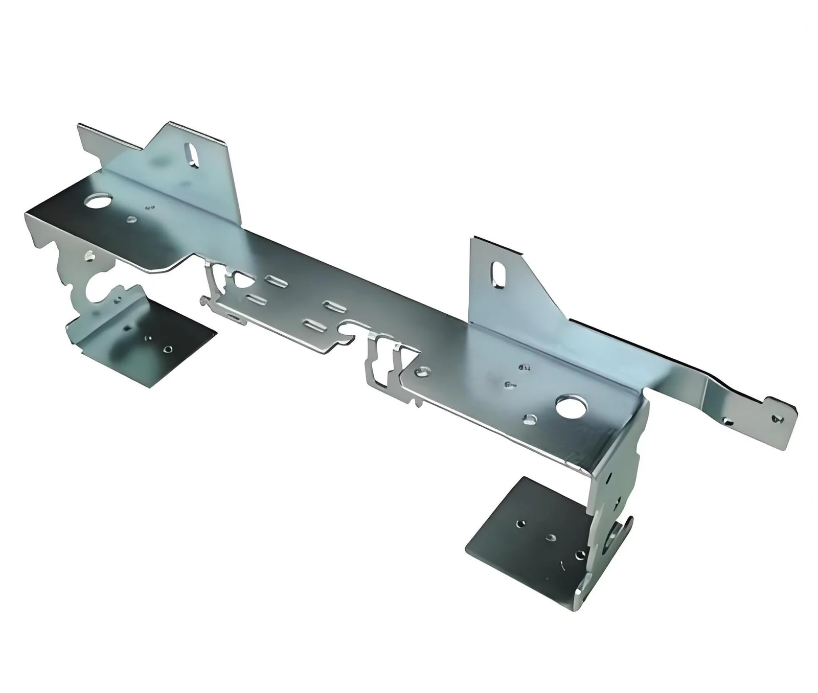
Installation tool clearance
The rivet axis is only the center of the installation envelope. The nosepiece, tool body and approach stroke need space, while the blind side needs room for the selected fastener to form. Model those envelopes against the actual assembly sequence.
GESIPA’s standard blind-rivet range lists hole, head and body dimensions separately. These dimensions explain why insertion clearance alone is insufficient: a rivet that enters a hole may still be impossible to set squarely against a nearby wall.
Check the worst accessible position, not the most open one. A tool tilted to avoid a return flange can change head seating and produce an installation condition absent from the qualification coupon. Reordering assembly can help, but only if later parts do not conceal an inspection surface or trap an unserviceable joint.
Record the proposed tool and nosepiece when clearance is tight. A supplier substitution with a larger front envelope may invalidate the assumed access. Discuss such constraints during a fabricated assembly review, alongside the blind-side formed-head envelope and removal route for temporary clamps.
Validate the joint with the real sheet stack
Qualification needs the same load-bearing stack that production will use. Include the specified sheet grade and condition, thickness range, hole-making method, finish and fastener designation. Substituting a thicker coupon or an unfinished flat sheet can remove the very mechanism being assessed.
Use boundary specimens to challenge the smallest ligament and the least favorable stack within the released drawing. If the expected load is eccentric, reproduce that offset in the fixture. Distinguish a specimen used to discover a failure mechanism from one used to demonstrate an agreed acceptance criterion.
The test report should identify where deformation begins and how failure progresses. A peak force alone cannot distinguish edge tearing from fastener breakage or fixture slip. Photographs before and after the test make that distinction reviewable.
NIST’s uncertainty-analysis guidance explains why a result needs an assessment of its measurement quality before it supports a decision. Apply that principle to force measurement and dimensional checks. Test-machine display resolution alone does not establish the uncertainty of a joint test that includes fixture alignment and specimen variation.
Finished-edge measurements to attach to the drawing
A useful drawing separates geometric margin from installation and service requirements. Connecting each requirement to its inspection state prevents a flat blank inspection from being mistaken for final assembly acceptance. It also shows which decisions belong to design and which remain manufacturing proposals.
Use the following matrix as a requirements map. The entries deliberately avoid generic numerical margins; the released product design and qualification establish those values.
| Requirement | Reference condition | Evidence |
|---|---|---|
| Edge ligament | Finished trimmed edge and actual hole | Dimension report at minimum allowed margin |
| Grip | Compressed production stack | Selected fastener designation and stack limits |
| Setting access | Assembly sequence and tool envelope | Tool approach review or witnessed trial |
| Load resistance | Installed load direction and offset | Qualified joint specimen and failure record |
Attach identifiers to the relevant joints if a product contains several flange arrangements. A shared fastener part number does not make their margins or load paths equivalent. Where the nearest edge changes after trimming or bending, show that edge directly in the inspection view.
A load fixture that preserves the critical ligament
Consider a hypothetical bracket with a riveted overlap loaded toward the end of one flange. A flat lap coupon can investigate edge tearing, but a coupon clamped directly beside the hole may be much stiffer than the installed bracket. The qualification fixture should preserve the load introduction that matters.
Make one specimen series represent the minimum finished margin and another represent any materially different access or forming condition. Change one deliberate variable at a time when investigating a cause. Otherwise a better result cannot be attributed confidently to margin, hole quality or grip correction.
Mark the sheet orientation, loaded edge and rivet setting side on every specimen. Preserve installation observations so a poorly seated fastener is not treated as a mysterious structural outlier.
NIST’s measurement-process variability discussion identifies variation as part of measurement characterization. Repeated positioning and testing should therefore be considered separately from the spread between manufactured specimens. This distinction helps determine whether inconsistent results come from the joint, the fixture or the way the test is carried out, rather than averaging unlike causes into one apparently tidy value.
Edge damage, permanent movement and joint acceptance
Agree acceptance before testing. Requirements can include load resistance, permanent deformation, head seating, sheet cracking and allowed movement, but each must correspond to the product’s function. A joint may retain ultimate strength while allowing movement that spoils alignment or a seal.
Measure the edge and hole location before the test and record the installed condition afterward. That establishes whether a failed specimen represented the released geometry. Inspect the loaded edge for cracks or tearing rather than relying only on the final separation photograph.
Treat fixture movement as a separate observation. A displacement taken from the crosshead includes the test arrangement unless the method isolates joint movement. State where displacement is measured and what its acceptance limit represents.
The standards and tolerances reference can support drawing discussions, while the actual product limits must remain on the controlled specification. Record deviations and their disposition explicitly. Acceptance of a development coupon with a known defect should never become an undocumented waiver for the production joint.
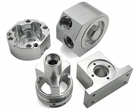
Margin and access evidence for the assembly quotation
Supply the joint section, finished-part drawing, fastener designation and loading explanation with the quotation request. Add the minimum available margin, the hole-making route if already constrained, and the installation sequence. These details let manufacturing distinguish an ordinary riveting operation from a joint requiring dedicated access checks or qualification work.
Identify unresolved choices clearly. If a wider flange, another fastener family or a revised assembly order remains available, state the functional constraints that alternatives must preserve. This makes a manufacturability proposal useful without allowing an unnoticed design change.
Define the requested evidence package: dimensional results for the finished edge, installation observations, specimen identities and the agreed load-test record. For repeat orders, retain the relationship between those records and the released drawing revision.
NIST’s metrological traceability policy concerns measurement results and documented calibration relationships. It does not mean a supplier logo or a calibrated instrument automatically validates this joint. Ask for the evidence relevant to the acceptance decision, including the method and conditions, instead of using traceability as a substitute for a demonstrated load path.
FAQ
Does increasing rivet diameter always improve an edge-critical joint?
No. A larger hole removes more sheet from the ligament and may require a different head, grip range and setting envelope. It can improve one fastener-related limit while making sheet tearing or packaging more restrictive. Review the full joint rather than scaling only the rivet. If diameter changes during development, repeat the relevant geometry and installation checks and determine whether the earlier qualification still represents the revised configuration.
Can an edge-damaged prototype be used for qualification?
It can help investigate how damage affects the joint, but it should not quietly represent an undamaged production requirement. Identify the damage, photograph its location and explain the test purpose. If comparable damage is permitted in production, define its acceptance boundary and include that condition deliberately. Otherwise use conforming specimens for acceptance testing and retain the damaged sample as separate development evidence with its own disposition.
Should every rivet in an enclosure have the same edge distance?
Only when the different joints support that choice. Loads, sheet thickness, edge geometry, installation access and neighboring features can differ across an enclosure. A shared dimension can simplify inspection, but it should follow an engineering assessment of those locations. Identify the critical joint families and qualify their representative boundaries. Do not transfer approval from an accessible flat overlap to a tight corner solely because both use the same rivet.
Conclusion
Release the hole location only when the finished ligament, installation access and actual load path agree. Edge distance is a geometric input to that decision; the acceptance evidence comes from a defined joint in a defined condition. A ratio without the sheet, hole and loading assumptions leaves the most important engineering question unanswered.
Preserve the qualification boundary when production changes. A new trimming process, fastener substitution or assembly sequence may affect a different part of the evidence than a simple dimensional revision suggests. Review the changed mechanism and keep the disposition with the drawing.
For a manufacturing review, upload the bracket CAD, rivet details and joint acceptance requirements for a quotation. 6CProto’s DFM review can then address the actual formed geometry and the information needed to evaluate the assembly route.