

A sealed enclosure is a compression system with a housing around it. The seal depends on a gasket being compressed by a known amount between two surfaces that stay flat and parallel under load, and every design decision that affects stiffness, flatness or fastener spacing feeds directly into whether the product passes an ingress test. This guide covers what an IP rating actually requires, how wall thickness and gasket geometry interact, how to space fasteners so the joint stays closed, and what to verify before the design is released for machining.
What does an IP rating actually require?
A verified performance level, not a design label.
An IP rating describes tested resistance to dust and water ingress, and it is demonstrated by test rather than by the presence of a gasket.
The rating has two digits. The first describes protection against solid objects and dust, and the second describes protection against water, from light dripping through to immersion. The definitions are published in the international standard that covers enclosure ingress protection, and the tests that demonstrate each level are specified there rather than left to interpretation.
What matters for design is that the rating is a whole-enclosure property. A gasket alone does not confer a rating; the enclosure must keep the gasket compressed, the housing must not deflect under the test conditions, and any cable entries, connectors or windows must provide the same level of protection as the main joint. Products frequently fail a test at a cable gland rather than at the sealing face, which is why the mechanical design and the interface design have to be considered together.
The requirement should also be stated as a test condition rather than as a number. A product that must survive temporary immersion is a different design problem from one that must resist hose-directed water, even though the two might be described in similar terms in a specification. Naming the test that applies removes the ambiguity before the design is committed.
How do wall thickness and stiffness support sealing?
The housing has to hold the gasket, not just contain it.
Compressing a gasket requires force, and the housing must be stiff enough that the force is transferred to the gasket rather than deflecting the cover.
The sealing load is a design input. A gasket is compressed by a percentage of its section, and the force required to achieve that compression depends on the gasket material, the cross-section and the length of the seal. The housing and cover have to carry that force without bowing, because any deflection between fasteners reduces the compression on the gasket in that span.
Two design responses follow. Increasing wall thickness or adding ribs raises the stiffness of the cover, which keeps the compression more uniform but adds material and weight. Reducing fastener spacing achieves the same result with less material, at the cost of additional screws and assembly time. The two approaches can be combined, and where the enclosure is large, ribs and spacers are usually the practical answer.
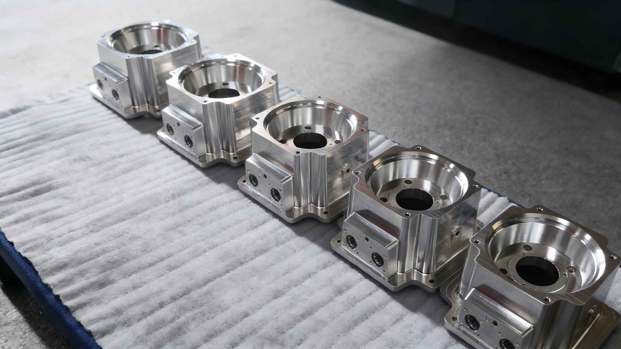
Flatness matters as much as stiffness. A cover that is flat when it is manufactured can distort when it is tightened, particularly where the fasteners are unevenly spaced or where the gasket load is concentrated. A machined cover face gives the design a flat starting surface, which is one reason machined sealing faces are preferred where the requirement is demanding.
How should a gasket groove be designed?
To control compression and hold position.
A groove limits how far the gasket can be compressed, holds it in place during assembly and defines the sealing line relative to the fasteners.
Compression is the parameter the groove controls. The groove depth is set so that, when the joint closes, the gasket is compressed by the amount its material requires and no more. That prevents over-compression, which takes a permanent set and leaves the seal ineffective on reassembly, and under-compression, which leaves a gap. The groove width accommodates the gasket’s volume as it compresses, so a groove that is too narrow prevents the joint from closing at all.
Position is the second function. A groove keeps the gasket aligned during assembly, which matters for a long perimeter or a complex shape where a loose gasket could shift. It also locates the seal line deterministically relative to the fastener pattern and the housing walls, which is what allows the compression to be predicted rather than estimated.
Manufacturability constrains the groove as well. Corners carry the radius of the cutter that produced them, so a groove with sharp internal corners cannot be machined as drawn; the gasket must accept the radius the tool leaves. Groove depth is limited by the same tool-access rules that govern any pocket, which is why a deep, narrow groove on a large enclosure is a costly feature. The tolerance framework for those features is set out on 6CProto’s standards and tolerances page.
| Element | What it controls | Consequence if wrong |
|---|---|---|
| Gasket cross-section | Compression range and sealing force | Leaks or over-compression |
| Groove depth | How far the gasket is compressed | Joint will not close, or seal is loose |
| Groove width | Space for the compressed gasket | Joint bottoms out before sealing |
| Wall and cover stiffness | Uniform compression between fasteners | Leak path in the middle of each span |
| Fastener spacing | How evenly the joint closes | Cover bows; compression varies |
| Sealing face finish | Whether the gasket can conform | Leakage along tool marks |
How should fasteners be spaced and loaded?
Close enough that the joint never opens between them.
Fastener spacing is set by how much the cover deflects under gasket load, so it follows from the cover’s stiffness rather than from convenience.
The relevant question is how far the cover can span between two fasteners without losing contact with the gasket. A stiff cover with a wide span still compresses the gasket evenly; a flexible cover with the same spacing bows in the middle and leaves the gasket under-compressed exactly where the leak would appear. That is why increasing the number of fasteners is often the cheapest fix for a sealing problem, while thickening the cover is the more expensive one.
Fastener type matters less than load, but it is not irrelevant. A screw tightened to a defined torque produces a predictable clamp load; a screw tightened by feel does not, which introduces variation between assemblies. Where the seal has to be repeatable in production, specifying a torque and verifying it on first article is a modest addition with a real effect.
Compression limiters are the third option. A shoulder, a step or a spacer stops the joint closing beyond a set point, which protects the gasket from over-compression regardless of how much torque is applied. In designs where a seal must survive repeated opening and closing, the limiter is what keeps the gasket’s compression within its working range over many assembly cycles.
How do EMI gaskets and shielding interact with sealing?
They share the joint, and they compete for space.
Where a product needs both ingress protection and electromagnetic shielding, the joint has to carry two sealing functions in one groove or in adjacent features.
An EMI gasket works on a different principle from an environmental seal. Its purpose is to maintain electrical continuity across the joint, so it needs contact with conductive surfaces on both sides and a low-impedance path across the seam. The environmental gasket needs compression in the direction of the joint, which is usually the same direction.
Two arrangements are common. A single gasket can be specified to perform both functions, which requires a material and geometry that conduct and seal, and a groove designed to keep it compressed. Alternatively, the two functions are separated: an environmental gasket seals the outer perimeter and a conductive gasket or finger strip provides continuity along an inner or adjacent path.
Coating is the practical complication. Any coating on the housing interrupts electrical continuity, so the surfaces where the EMI gasket contacts must be masked or made conductive by another means. That requirement belongs in the finishing specification rather than being discovered after the parts are coated and the shielding test fails.
How is a sealed enclosure tested?
By the test the rating requires, on a complete assembly.
Ingress testing is performed against the specific conditions the rating defines, and supplementary leak tests are used in production to verify the assembly.
The ingress test itself is defined by the standard for the rating claimed. It may involve dust exposure, water spray, jetting or immersion, each with its own duration and conditions, and the test is applied to a complete enclosure rather than to a housing. That is why cable entries, connectors, ventilation features and any window must be fitted for the test and must offer the same protection as the joint.
For production, a pressure or vacuum leak test is the practical check. The enclosure is pressurised slightly, or evacuated, and the pressure change over a defined period indicates whether it seals. The method is repeatable, quick and non-destructive, and it verifies the assembled product rather than the presumed design. The correlation between a leak test result and the ingress rating is established on the first articles rather than assumed.
Visual inspection of the sealing face before assembly catches the other common failure: contamination, a scratch or a coating on the sealing surface that prevents the gasket from seating. On machined enclosures with a masked sealing face, that check is quick and worth specifying.
What belongs in the design review before machining?
The gasket, the groove and the stiffness, checked together.
A design review before machining should confirm that the gasket has room to compress, that the housing can carry the load, and that every entry point offers the same protection.
The list is short and specific. The gasket cross-section and its required compression range, the groove dimensions that produce it, the cover stiffness and fastener spacing that keep compression uniform, the finish of the sealing faces, and the treatment of every penetration through the enclosure. Where the product needs shielding, add the conductive surfaces and their masking.
Machinability then constrains the groove: its depth, width and corner radii have to be producible by a standard tool. Raising a groove that is too deep, or accepting the radius the cutter leaves, is a design change that costs nothing on paper and a great deal after machining. 6CProto reviews enclosure designs for manufacturability before production and returns a DFM report with the quote, so those features can be adjusted while the design is still open.
Designing a seal that passes the test
A sealed enclosure works when the gasket is compressed by a controlled amount across a flat, stiff joint, and it fails when any of those three conditions is not met. Wall thickness and fastener spacing set the stiffness, the groove sets the compression, and the surface finish of the sealing face decides whether the gasket can conform. Testing then verifies the assembly rather than the intention.
The practical sequence is to choose the gasket first, design the groove around its compression range, then size the housing and the fastener pattern to carry the load. Reviewing that against machinability before the design is released removes the surprises, and a leak test on the first article confirms that the assembly behaves as the design predicted. The wider enclosure design routes are described in the 6CProto article on sheet metal enclosure design for IP, EMI and thermal requirements, and the quality practices behind production testing are published by NIST MEP.
FAQ
What is an IP-rated enclosure?
It is an enclosure that has been tested against the ingress protection conditions defined in the international standard and rated according to the result. The first digit covers solids and dust, the second covers water. The rating applies to the complete assembly, including cable entries and any windows, which is why a product can pass on the housing and still fail at a gland that was not specified to the same level.
How do you design a waterproof enclosure?
Start from the gasket: choose its cross-section and compression range, then cut a groove that produces that compression when the joint closes. Size the cover and set the fastener spacing so the compression stays uniform between fasteners, specify a sealing face finish that the gasket can conform to, and treat every penetration as part of the seal. Verify the result with a leak test on the first article.
Is IP67 or IP68 more waterproof?
IP68 is the more demanding of the two in terms of water, because it covers continuous immersion under conditions agreed between the manufacturer and the test house, while IP67 covers temporary immersion under defined conditions. Which one a product needs depends on its use rather than on a general preference, and the test conditions for IP68 have to be specified by the parties because the standard leaves them open.
Why does a sealed enclosure leak at the middle of a side?
Usually because the cover deflects under the gasket load and loses compression between fasteners. The span between two fasteners behaves like a beam, and a cover that is not stiff enough bows outward in the middle of that span, reducing the squeeze on the gasket exactly where the leak appears. Adding fasteners is the cheaper remedy; thickening the cover or adding ribs is the more material-intensive one. The standards, materials data and regulatory framework referenced in this article are published by ASTM committee B08, ASTM D3359, ASTM committee D20, ASTM committee E28.
If an enclosure has to pass an ingress test, send the model with the gasket you intend to use, the IP requirement and the entry points that must also seal. 6CProto reviews the design for manufacturability and returns a DFM report with the quote, so the groove, the wall sections and the fastener pattern are settled before machining. Upload the file at the 6CProto quote page or send it to projects@6cproto.com.