

Explore Quality, DFM & Procurement Guides
A press fit chart is a table of fits grouped by nominal size, and it is easy to use incorrectly. The numbers describe the relationship between a hole and a shaft, so a chart entry is meaningless unless both parts are specified to the grades it assumes.
What the numbers in a chart represent
Standard fit tables are built from two elements. The first is the fundamental deviation, which sets where the hole or shaft tolerance zone sits relative to the nominal size and is denoted by a letter. The second is the tolerance grade, denoted by a number, which sets how wide that zone is. A letter and a number together define a tolerance such as a hole with an H designation or a shaft with a p designation, and a fit is described by pairing them.
| Element | What it controls | Effect on the fit |
|---|---|---|
| Letter (deviation) | Position of the tolerance zone relative to nominal | Determines whether clearance or interference results |
| Number (grade) | Width of the tolerance zone | Determines how much variation the fit tolerates |
| Hole basis | Hole kept at nominal, shaft varied | Most common shop practice |
| Shaft basis | Shaft kept at nominal, hole varied | Used where shafts are bought finished |
How to read a chart for a real joint
Work through four steps. Find the row for the nominal diameter, since fits are tabulated by size range. Identify the hole tolerance the chart assumes, usually an H grade. Identify the shaft tolerance paired with it, which is what produces the clearance or interference. Then read the resulting minimum and maximum values and check them against what the joint has to do.
The step most often skipped is the last one. A chart tells you what a pair of grades produces; it does not tell you whether that is right for a hub wall thickness, a service temperature or an assembly method. Treat the chart as a vocabulary for describing fits rather than as a decision, and the specification becomes much more reliable.
Why dowel pin fits differ from shaft fits
A dowel pin in a plate and a shaft in a hub are both interference fits, but they distribute deformation differently. In a shaft and hub joint, both parts are substantial and the stiffness of each contributes to the contact pressure. In a dowel pin joint, the pin is hard and effectively rigid while the plate around it is thin by comparison, so nearly all the elastic deformation happens in the plate. The consequence is that a pin fit must use less interference for the same nominal size, or the plate will yield, distort or crack.
Two practical differences follow. Pin holes are normally reamed to achieve a round, consistent bore, because a drilled hole is seldom round enough to give predictable interference. And pin fits are usually specified with reference to the plate material, since a soft aluminium plate and a hardened steel plate behave very differently around the same pin.
How hole tolerance affects the interference you actually get
The interference in an assembled joint is not the difference between the nominal sizes; it is the difference between the actual dimensions of the two parts as produced. That means both tolerances contribute, and the worst case is the smallest hole paired with the largest shaft. The chart’s minimum and maximum figures already account for that, which is why the range is wider than a single nominal interference value.
Two consequences are worth planning for. Widening either tolerance widens the interference range, so a fit that is marginal at the extremes may produce joints that are too loose for some assemblies and too tight for others; a tighter grade on either part narrows the range but adds cost. And surface finish contributes directly, since roughness on the mating surfaces is compressed during assembly and consumes a portion of the theoretical interference.
Applying a chart to a specific design
Start with the load the joint must carry, then check the material and wall thickness, then check the service temperature for differential expansion, and only then select the fit from the table. If the selected fit produces stresses near the material’s limit, or if the required assembly force exceeds what the press can deliver, the design needs revisiting rather than a tighter tolerance.
Two habits make the result manufacturable. Choose a fit whose tolerance band can be produced on the equipment that will make the parts, because an ideal fit that cannot be held consistently is worse than a slightly looser one that can. And specify the fit as a pair on the drawing, using a conventional designation, so that both parts are made to the same assumption rather than to independent general tolerances. Drawing conventions follow ASME standards, dimensional verification practice is described by the NIST Manufacturing Extension Partnership, and surface terminology follows ASTM Committee B08.
Where charts stop being enough
Three situations need more than a table. When the joint carries significant torque or axial load, because the required contact pressure has to be calculated rather than looked up. When the two materials have very different expansion coefficients and the joint operates over a temperature range, because the interference at service temperature may differ from the assembly condition. And when one of the parts is thin-walled, because the standard assumption of a substantial hub no longer holds.
In those cases the chart provides a starting point and a vocabulary, not an answer. The engineering work is to check contact pressure, stress in both parts and the assembly method, and then to specify tolerances that the shop can actually hold. Material behaviour references for the two components are published by ASM International, and the finishing obligations that apply to the parts are set out by the US EPA. Related tolerance guidance is collected under standards and tolerances, and the machining routes for tight fits are described under precision machining.
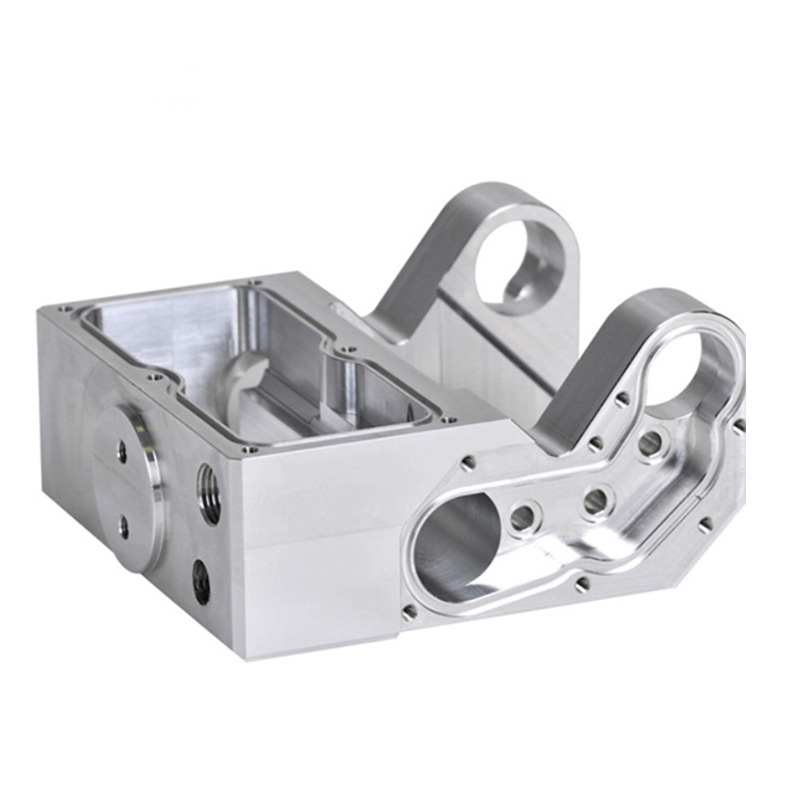
Send the mating parts with the fit designation and the load, and request a quote for bores and shafts produced as a matched set.
FAQ
How do you read a press fit tolerance chart?
Find the row for the nominal diameter, identify the hole grade the chart assumes, identify the shaft grade paired with it, then check the resulting minimum and maximum interference against the joint’s requirements rather than treating the entry as a recommendation.
What is the difference between a dowel pin fit and a shaft fit?
In a shaft and hub joint both parts are substantial and share the deformation. A dowel pin is hard and effectively rigid, so nearly all deformation occurs in the plate, which means less interference is used and holes are reamed rather than drilled.
How does hole tolerance affect the interference you get?
Interference is the difference between the actual dimensions, so both tolerances contribute and the worst case is the smallest hole with the largest shaft. Widening either tolerance widens the range, while surface roughness consumes part of the theoretical interference during assembly.