

Explore Quality, DFM & Procurement Guides
An ISO tolerance designation looks like a code because it is one. The letter and number in something like H7 or p6 describe where a tolerance zone sits and how wide it is, which means a table can be read rather than memorised.
What an ISO tolerance designation contains
Two elements make up the designation. The letter indicates the fundamental deviation, which is the position of the tolerance zone relative to the nominal size: a capital letter is used for holes and a lower-case letter for shafts. The number indicates the tolerance grade, which sets the width of that zone. Together they define the permitted limits for that dimension, and the actual values are tabulated by nominal size range.
| Element | Meaning | Practical effect |
|---|---|---|
| Letter | Position of the zone relative to nominal size | Decides whether the result is clearance or interference |
| Number | Tolerance grade, from fine to coarse | Decides how much variation is permitted |
| Capital letter | Applied to a hole | H indicates the hole is nominally at size |
| Lower-case letter | Applied to a shaft | Lettered shaft zones produce the various fits |
What the ISO standard for tolerances covers
The core standard in this family is ISO 286, which defines the ISO code system for limits and fits on linear dimensions. It establishes the tolerance grades, the fundamental deviations and the way the two combine into a fit. Alongside it sit the companion standards that cover general tolerances for dimensions without individual callouts, geometric tolerances, and the verification of the resulting dimensions.
The practical consequence is that a drawing does not need to carry numeric limits for every dimension. It can state a general tolerance for the drawing and apply individual fits only where the function requires them, which keeps the drawing readable and concentrates inspection where it matters. That structure is what makes an ISO-based drawing efficient rather than merely compliant.
What the tolerance table actually shows
A table from ISO 286 is organised by nominal size range across one axis and by tolerance grade along the other, with the resulting upper and lower deviations in each cell. Because the permitted variation scales with size, the table is divided into ranges rather than listing every possible diameter. Reading the table therefore means finding the size range, then the grade, then the deviation for the letter in question.
Two points are easy to miss. The values are deviations from the nominal size, not absolute dimensions, so the nominal must be known before the table can be used. And a fit is defined by the combination of a hole and a shaft designation, which means the table alone does not tell you whether a joint will be loose or tight until both parts are chosen. Related guidance is collected under standards and tolerances.
How to calculate an ISO tolerance for a specific dimension
Work through four steps. Identify the nominal size and confirm which size range it falls in. Identify the fundamental deviation letter, which fixes where the zone sits relative to nominal. Identify the tolerance grade number, which fixes the width of the zone. Then apply the tabulated deviations to the nominal size to obtain the upper and lower limits.
The reason this is presented as a procedure rather than a formula is that the underlying calculation is size-dependent and is normally taken from the published table. What matters for design is understanding which of the two variables changes the fit: changing the letter moves the zone and therefore changes the nature of the fit, while changing the number only widens or narrows it. That distinction is the key to using tables efficiently rather than looking up a value for every dimension. Verification practice is described by the NIST Manufacturing Extension Partnership.
Using the system to control cost
The grade number is where cost lives. A finer grade requires a more capable process, more careful setup and more inspection, so specifying a fine grade everywhere raises the price of every dimension it touches. A coarser grade accomplishes the same fit on a non-functional dimension at a fraction of the cost, and the design is no worse for it.
The efficient structure is to choose a general tolerance for the whole drawing, apply specific fits only at the interfaces that carry function, and leave everything else coarse. That approach is not a compromise on quality; it is what the standard is designed to support. Drawing conventions follow ASME standards, material references for the parts involved are published by ASM International, and surface terminology follows ASTM Committee B08.
Where the system stops and engineering starts
A table tells you what a combination of grades produces; it does not tell you whether that result is right for your joint. Three situations require more than a lookup. When the joint carries significant load, because the required contact pressure or clearance has to be calculated. When differential thermal expansion between the materials is significant over the service range. And when one part is thin-walled, because the standard assumptions about rigidity no longer hold.
In those cases the table gives a starting point and a vocabulary, and the rest is design work. The practical habit is to specify the fit as a pair using the designation, state the load and the temperature range, and confirm with the shop that the chosen grade can be produced consistently on the equipment that will make the parts. Machining for tight fits is described under precision machining, and process obligations are set out by the US EPA.
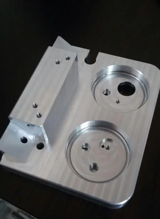
Send the part with the fits that matter and the general tolerance you intend to use, and request a quote with the achievable grades stated.
FAQ
What is the ISO standard for tolerances?
ISO 286 defines the code system for limits and fits, including the tolerance grades and fundamental deviations. Companion standards cover general tolerances for dimensions without individual callouts, geometric tolerances and verification of the resulting dimensions.
What is the ISO 286 tolerance table?
It is the table of deviations organised by nominal size range and tolerance grade, giving the upper and lower limits produced by each letter and number combination. Values are deviations from nominal, so the nominal size must be known first.
How do you calculate an ISO tolerance?
Identify the nominal size and its size range, find the fundamental deviation from the letter, find the tolerance width from the grade number, then apply the tabulated deviations to the nominal size. Reading the published table is normal practice, since the values are size-dependent.