

Explore Quality, DFM & Procurement Guides
A fit chart is a menu of relationships rather than a set of dimensions. The useful question is not which entry looks best on paper, but which combination of hole and shaft the shop can produce consistently on the parts in front of it.
What a fit chart describes
Every charted fit is a pair: a hole tolerance and a shaft tolerance that together produce a predictable range of clearance or interference. The three families are clearance fits, where the shaft is always smaller; interference fits, where it is always larger; and transition fits, which can produce either depending on where the actual dimensions land. The chart shows the minimum and maximum result for each pairing.
| Family | Result | Typical use |
|---|---|---|
| Clearance fit | Shaft always smaller than hole | Sliding and rotating joints, locating with movement |
| Transition fit | Either clearance or slight interference | Accurate location that can be assembled by hand |
| Interference fit | Shaft always larger than hole | Permanent joints transmitting load or torque |
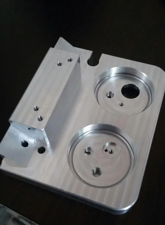
What the standard tolerance between a shaft and a hole is
It depends on the function, the size and the materials.
There is no default tolerance that applies between a hole and a shaft, because the required relationship follows from what the joint has to do. A shaft that must rotate freely needs a positive clearance at all conditions, including thermal growth. A pin that must hold a plate in position needs a small interference or a very tight clearance. A locating boss that must centre a cover needs a fit tight enough to control position but loose enough to assemble without force.
What the standards provide is a vocabulary for describing those requirements and a table of the deviations that produce them. Choosing a fit means deciding first what the joint must achieve, then selecting a pair whose minimum and maximum results satisfy that requirement, then confirming that both parts can be made to the chosen grades. Working in that order is what prevents the common situation of a fit chosen for appearance that no one can hold in production.
Typical tolerance for a drilled hole, and why it changes with the method
The tolerance on a hole depends far more on how it is produced than on the nominal size. A drilled hole is subject to drill wander, entry and exit burrs, and a slight lobing that is seldom visible but affects measurement; its achievable tolerance is looser than most designers expect. Reaming after drilling produces a rounder, more consistent and more accurately sized hole. Boring gives better control again and can correct position as well as size. And a machined bore in a milled or turned part can be interpolated to a controlled size with predictable results.
The practical consequence is that a fit requiring a tight hole should specify the process that produces it, or at least the resulting tolerance, rather than relying on a drilling operation to deliver it. Where a drawing calls for a close hole tolerance with no indication of how it will be made, the shop has to choose between an operation the customer did not pay for and a tolerance that will not be met.
How to find the tolerance for a hole on a drawing
Look at the dimension and its callout. If it carries a tolerance value or a fit designation, that governs. If it has no individual callout, the general tolerance note on the drawing applies to it. And if the drawing references a standard for general tolerances, that standard supplies the permitted variation for that size range.
Three practical points follow. Individual callouts override the general note, so a drawing can be coarse overall and precise where it matters. The general tolerance applies to the dimension as measured, which means the measurement method has to be consistent with the intent. And a fit designation appearing next to a dimension means both parts of the pair must be made to the corresponding grades, not only the one the callout is attached to. Verification practice is described by the NIST Manufacturing Extension Partnership, and drawing conventions follow ASME standards.
Choosing a fit the shop can hold
Four questions make the choice practical. What is the nominal size, because fits are tabulated by size range. What must the joint do, because that sets whether clearance or interference is needed. What is the wall thickness and material around the hole, because a thin wall cannot develop the contact pressure a thick one can. And how will each part be produced, because the achievable grade depends on the process.
Two habits improve the result. Specify the fit as a pair using a conventional designation, so both parts are made to the same assumption. And confirm with the shop which of the pair is easier to control: on some parts it is the bore, on others the shaft, and that determines which grade should carry the tighter tolerance. Surface terminology follows ASTM Committee B08, material references are published by ASM International, and process obligations are set out by the US EPA. Machining routes for these features are described under precision machining.
Where charts are not enough
Three cases need calculation rather than lookup. Where the joint transmits torque or axial load, because the required interference has to be derived from the contact pressure needed. Where the assembly operates across a temperature range and the two materials expand differently. And where one part is thin-walled, because the standard assumption of substantial components does not hold and the deformation concentrates in the thinner part.
In each case the chart provides the starting point, and the design work is to check stress in both parts, the assembly method and the behaviour at service temperature. That sequence keeps the specification honest and produces a joint that works rather than one that merely looks correct on a drawing.
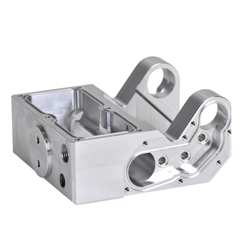
Send the mating parts with the function each joint has to perform, and request a quote for bores and shafts produced as a matched pair.
FAQ
What is the standard tolerance between a shaft and a hole?
There is no single default, because the required relationship follows from the function, the size and the materials. Standards provide a vocabulary and tables of deviations; the fit itself is chosen from what the joint must achieve, then confirmed as producible.
What is the typical tolerance for drilled holes?
It is looser than most designers expect, because drilling is subject to wander, lobing and burrs. Reaming produces a rounder and more accurate hole, boring gives better control still, and an interpolated bore in a milled or turned part is predictable.
How do you find the tolerance for a hole on a drawing?
An individual tolerance value or fit designation governs; otherwise the drawing’s general tolerance note applies, or the referenced general tolerance standard supplies the limits for that size range. Individual callouts always override the general note.