

A plastic profile that measures perfectly at the extruder arrives undersized at the customer, because the profile kept shrinking after it was cut and cooled. Plastic extrusion tolerances are a material behavior story: the profile is shaped hot and cools to its final size, and the shrinkage, the cooling, and the die balance all move the dimensions. Specifying plastic extrusion tolerances means understanding how the material behaves and writing the tolerance for the real profile, not copying an aluminum or a metal table.
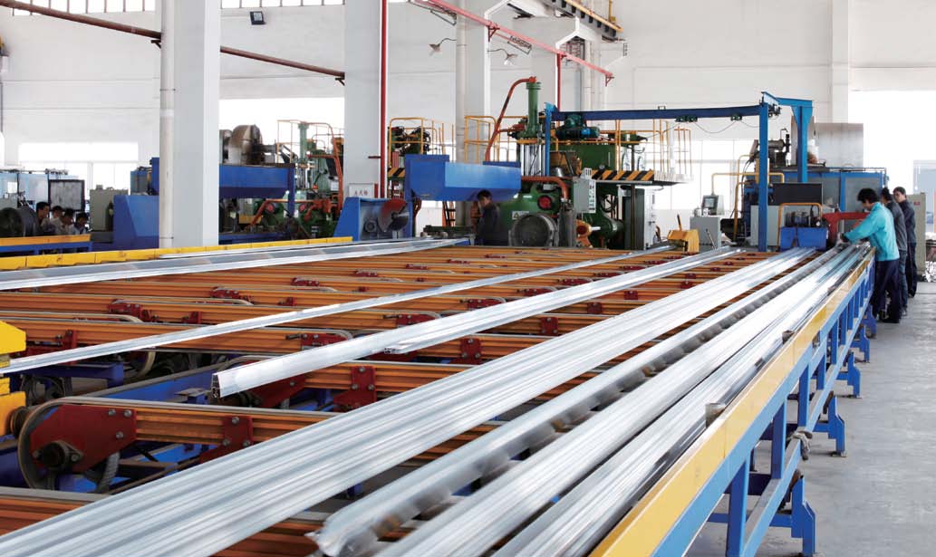
Why plastic profiles move: shrinkage, cooling, and die balance
Plastic profiles move as they cool. The melt leaves the die hot and is sized as it cools; the shrinkage varies with the material, the cooling rate, and the profile’s wall balance; and the die is designed with compensation for the expected shrink. The profile continues to move after the initial cooling — some materials continue to shrink or relax over time, and the profile’s dimensions at the extruder can differ from its dimensions after storage. The drawing should state the measurement condition and the time after extrusion, because the profile that is measured at the line is not the profile that arrives at the customer. The material behavior, not the drawing number, sets the achievable tolerance.
The cooling also affects the profile’s straightness and its internal stress: a profile cooled unevenly can bow or warp, and the cooling method is part of the process control.
Tolerance expectations by material family
The tolerance expectations differ by material family. PVC, flexible compounds, and the engineering plastics each shrink and move differently, and the achievable tolerances follow the material. Flexible profiles move more and hold looser tolerances than rigid ones; filled materials shrink less but can be harder to hold on thin features; and crystalline materials behave differently from amorphous ones. The tolerance should be set with the material’s behavior in view, and the material supplier’s data provides the shrink and the processing guidance. A tolerance that is standard for one material can be impossible for another, and the drawing should be reviewed against the actual grade before it is released.
The tolerance table from the extruder is the practical reference, because it is built from the material and the die experience rather than from a generic standard.
Profile features that are hard to hold: thin walls, long spans
Some profile features are naturally hard to hold. Thin walls move and can be difficult to keep uniform; long unsupported spans bow and sag; hollows with thin webs distort during cooling; and features near the die opening behave differently from those deeper in the profile. The design should recognize the hard-to-hold features and put the tolerance where the function needs it, loosening the rest. A profile that asks for a tight tolerance on a thin, unsupported web is asking for a process that cannot deliver it consistently, and the drawing should be adjusted or the feature redesigned. The extrusion design review should identify the hard features before the die is cut.
The hard-to-hold features also affect the die design and the cooling: the die can be balanced to help, but the limits are set by the material and the geometry.
Die compensation and tooling iterations
The die is designed with compensation for the expected shrinkage and flow, and the first trial reveals where the compensation was wrong. The die is adjusted and re-tried until the profile meets the drawing, and the number of iterations depends on the profile complexity and the tolerance. The tooling plan should include the trial iterations, because a complex profile with tight tolerances may need several die corrections before it runs. The die records — the trial results and the adjustments — become the reference for the production runs and for any re-cut. The profile that is qualified with its die records is a profile whose tolerances were achieved by design, not by luck.
The die trial should measure the profile the way the drawing specifies, at the defined condition, so the iterations converge on the requirement rather than on a moving target.
Specifying tolerances and straightness for plastic profiles
The drawing should specify the cross-section tolerances, the straightness and the twist over a defined length, and the cut-length tolerance, with the measurement condition stated. The straightness and the twist are measured over the reference length, and the profile should be allowed to rest before the measurement so the cooling movement has settled. The tolerance callout should mark the critical features and leave the rest to the profile’s general tolerance, because a profile with every dimension tight is expensive and no more functional. The measurement condition — the temperature and the time after extrusion — belongs in the specification, because the plastic profile moves and the measurement must be repeatable. The custom-extrusion materials and applications article covers the process scope; this page is the tolerance-specification guide that makes the drawing executable.
Qualifying the profile and its die
The profile qualification starts with the die trial and runs through the production verification. The trial profile is measured at the defined condition, the dimensions are compared against the drawing, and the die is adjusted until the profile meets the specification. The qualification should also verify the straightness, the twist, and the cut length over the reference length, and it should confirm the profile’s stability after the cooling and the resting period. The first production run is measured against the same standard, and the results become the baseline for the lot inspection. A profile that is qualified with its die and its measurement method is a profile whose tolerances were achieved by the process; one that is accepted from the trial without the full verification carries the variation into every production lot.
The qualification should also cover the profile’s behavior in service: the shrinkage after storage, the response to the service temperature, and the straightness after cutting and handling. The material’s behavior is part of the tolerance story, and the qualification should confirm that the profile holds the dimensions the application needs over its life. The die and the process records become the reference for the reorders and for the die maintenance, so the profile that is re-run later meets the same standard. When the profile is qualified and its behavior is documented, the extrusion tolerance is a controlled result — and the profile that ships is the profile the drawing promised.
The profile tolerance specification should also be connected to the secondary operations and the assembly. A profile that will be cut, drilled, or machined after extrusion carries the extrusion tolerance into those operations, and the finished feature tolerance should be set by the operation that makes it, not by the extrusion. A profile that will be assembled with a mating part needs the tolerance on the mating features, and the assembly clearance should be reviewed against the profile’s movement. The drawing should separate the extrusion tolerances from the secondary-operation tolerances, and the process notes should state which features are extruded and which are machined. The profile that is specified with its full route — the extrusion, the cutting, the machining, and the assembly — is a profile whose tolerances are allocated to the process that can hold them, and the finished part fits because each step was given the tolerance it could deliver. When the tolerance specification and the secondary operations are planned together, the plastic profile is an engineered component of the assembly rather than a material that the later steps must fight.
Keep the profile qualification and the measurement records with the die, so the reorders and the die maintenance reproduce the approved profile. The record is the reference for the lot inspection and the process control.
The final review should also cover the packaging and the handling, because a plastic profile can distort in storage and transit. The profile is supported and packaged so it arrives straight, and the receiving inspection measures it at the defined condition. The packaging note belongs with the tolerance specification, because the profile that is measured at the extruder and bent in transit has failed its requirement before it arrives.
Confirm the measurement condition and the resting time with the extruder, and state them on the drawing so the profile is measured the same way every time.
Confirm the resting time and the measurement condition with the extruder, and state them on the drawing so the profile is measured the same way at the line and at the receiving dock.
Confirm the extruder’s tolerance table and the die-trial plan before quoting, and verify the first production lot against the approved profile and its measurement condition.
Confirm the profile’s tolerance and its measurement condition with the extruder before release, and keep the qualification and the lot records with the die so the profile is reproducible across orders and reorders.
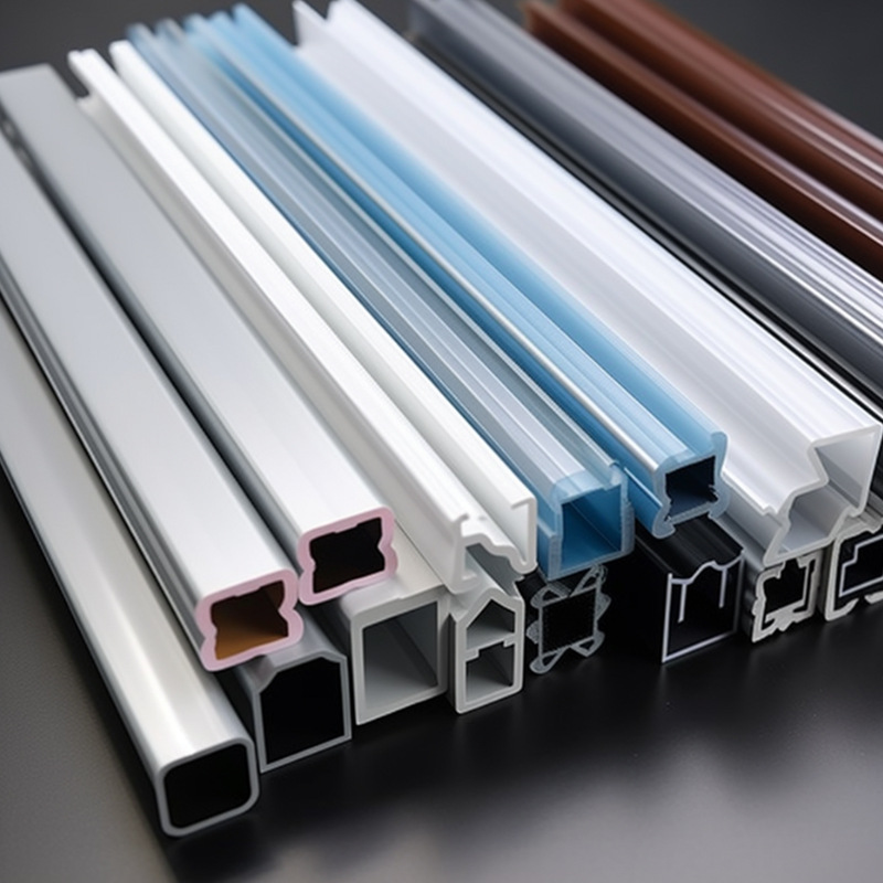
If you are specifying tolerances for a plastic profile and want the material behavior, the die, and the measurement plan reviewed, the 6CProto custom extrusion team can work from your profile geometry to the tolerance and the qualification plan.