

The moment a nylon part moves from a one-off prototype into a repeat order, the questions change. Nobody asks whether the geometry is printable any more; they ask whether the fifth batch will match the first, whether the price per part drops once the build is packed properly, and whether the supplier can hold a colour across a program. Multi Jet Fusion is often chosen precisely for those questions, because its build process is tightly controlled and its packing economics reward quantity. This guide covers what makes MJF repeatable, how nesting changes the price, which materials and finishes are available for production, and how to stage a move from prototype to bridge production.
Why does MJF suit repeat nylon batches?
Build parameters, not the operator, set the result.
A jetting platform prints fusing agent across each layer, so parts from different builds behave more consistently than in laser sintering.
Repeatability in powder-bed printing comes from how much of the process is machine-controlled. In a jetting system, the fusing agent is deposited by print heads and the energy source passes over the whole bed at once, which removes the variation that comes from steering a laser along individual part contours. The practical consequence for a buyer is that batch-to-batch differences are smaller and more predictable, which is what makes the process usable for parts that will be ordered again in three months.
That consistency is what turns a prototype into a bridge-production part. Bridge production exists because injection tooling takes time and money, and a program that needs parts before the tool is ready needs them to be consistent enough to assemble. Powder-bed nylon meets that requirement without tooling, and it also allows the design to change between batches without scrapping a mold.
The alternative is to treat each order as a new sample. Programs that do that accumulate small differences: a shade change here, a dimensional shift there, and eventually a batch that will not assemble. The rest of this article is about the details that prevent those differences.
How is a powder bed packed, and why does it matter?
Parts share one build, so height is the axis that costs.
Everything in the chamber is built in one pass, so a part that occupies more height consumes machine time no other component can use.
Packing is a three-dimensional nesting problem. Parts are placed in the chamber with clearance between them, and the arrangement has to respect thermal behaviour as well as volume: neighbours that sit too close can affect how a section cools, and parts near the edge of the chamber experience a different thermal environment from parts in the centre. A well-packed build therefore balances density against consistency rather than simply filling the available space.
Geometry decides how much freedom the packing has. Thin flat parts stack and nest with little wasted volume. Tall parts consume the height axis, which is the expensive one, and protrusions that stick out from an otherwise regular shape leave unusable gaps around them. Reducing overall height, even by splitting a tall part into two pieces that assemble, is often the single largest cost reduction available on a powder-bed part.
Quantity interacts with all of this. A part ordered alone is priced as a build cycle; the same part produced alongside other work shares that cycle, which is why a supplier running continuous powder-bed production can price differently from one who builds each order on its own. Asking how a quote assumes the bed will be loaded is a fair question and it usually explains the difference between two prices.
Which materials and colours are available for production?
The family is small, and the choice is behavioural.
Unfilled PA12 covers most production parts, PA11 and elastomeric grades add impact tolerance, and colour comes from dyeing rather than from the powder itself.
Material selection in MJF follows the same logic as in other powder-bed processes: match the grade to the load case. PA12 is the default for brackets, housings and fixtures where stiffness and predictable dimensions matter. PA11 and elastomeric powders shift the balance toward impact absorption and flexibility, which suits clips, covers and damping elements. Glass-filled grades raise stiffness and reduce creep where a part holds a sustained load. The Formlabs material library and the platform documentation published for HP Multi Jet Fusion describe the grades and their published properties.
Colour is a finishing decision rather than a material one. Parts arrive in the natural shade of the powder, which for most grades is grey, and colour is applied by dyeing after blasting. Dye penetrates the surface layer, so it does not chip, but the resulting shade depends on the base powder and on part thickness. Where a program needs a consistent colour, agree a reference sample and treat it as part of the acceptance criteria rather than a note in the purchase order.
What stays constant across builds?
Parameters, grade, orientation and finishing recipe.
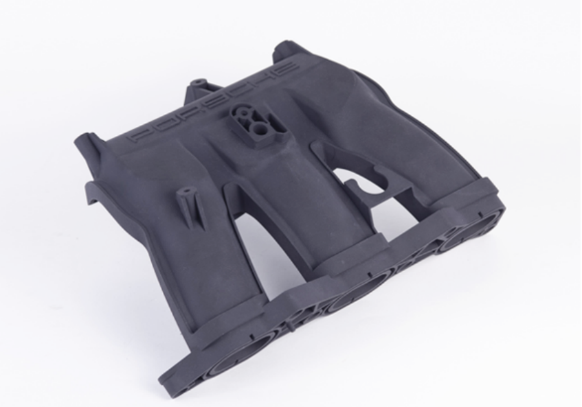
Repeatability is not automatic; it is the result of holding the same powder grade, the same build orientation, the same bed behaviour and the same finishing steps from one order to the next.
Four variables carry across orders. The first is the powder grade and its condition, since material that has been through many build cycles behaves differently from fresh powder. The second is orientation and bed position, which affect both dimensional spread and surface texture. The third is the finishing route, because blasting time and dyeing affect the final colour and surface. The fourth is the acceptance method, since a batch judged by a different method than the first can appear to fail when nothing has changed.
Recording those four items against the part number is what makes a reorder a production task rather than a new project. It also creates the evidence a buyer needs when an assembly works on the first batch and not on the fourth. Without the record, the conversation becomes a comparison of impressions; with it, the difference can be traced to a specific change.
For programs running over months, it is worth confirming that this record survives a change of project manager on either side, which is a reasonable question to ask any supplier during qualification.
Which design rules are specific to MJF?
MJF is forgiving on geometry and strict on sections.
The absence of supports removes overhang constraints, while uniform wall thickness and escape paths for powder become the rules that decide whether a part prints cleanly.
The design freedom is real: overhangs, internal channels, lattices and nested features all build without support structures, because un-fused powder holds the geometry in place. That is why MJF handles consolidated assemblies and complex internal routing that would need supports in resin or extrusion printing.
The constraints sit elsewhere. Wall thickness should be as uniform as possible, because a thick section next to a thin one cools at a different rate and can distort. Enclosed volumes need escape paths so powder can be removed. Fine details, small holes and finished threads are usually handled by designing a pilot feature and machining or tapping afterwards. And features that will slide or seal should be specified as machined faces rather than left as-built.
Because these rules interact with orientation, the design review is the right place to raise them. The 3D printing design tips library covers the shared geometry rules, and the terminology used in those conversations follows the additive manufacturing vocabulary maintained in ASTM F2792. Powder behaviour behind those rules, including how the grades compare after repeated build cycles, is documented by platform material suppliers such as EOS, and the measurement methods behind published property data are described in the NIST additive manufacturing program.
| Feature | Printed in MJF | Notes |
|---|---|---|
| Enclosed cavities | Yes, with escape paths | Powder must be removable after the build |
| Internal channels and lattices | Yes | No supports required; escape path still needed |
| Small holes and fine text | Limited | Often enlarged or drilled after printing |
| Threads | Pilots only | Tapped or fitted with inserts afterwards |
| Sealing or sliding faces | Requires machining | The as-built grain is not a sealing surface |
| Uniform wall thickness | Required where possible | Uneven sections distort during cooling |
How do you stage a move from prototype to bridge production?
In three orders, not one leap.
A prototype order confirms the geometry, a small batch confirms assembly and finish, and a bridge order carries the part until tooling is ready, with the parameters frozen between them.
The first order should answer a single question: does the geometry work? At that stage, the value of the part is in what it proves about fit, function and appearance, and the parameters that produce it are worth recording even though the part is a one-off.
The second order widens the test. Producing ten or twenty parts in one build reveals whether the packing arrangement introduces variation between positions, whether the finish is consistent across a batch, and whether assembly works when all the parts come from the same run. This is the order that most often exposes a design issue, because a single prototype hides variation that a batch makes visible.
The bridge order then runs with those parameters frozen, supplying parts while tooling is designed and cut. Its purpose is to remove schedule pressure from the tooling decision, and it works best when the acceptance criteria are the same as the previous batch. Where the design will change before tooling, the bridge part should be specified as an interim component rather than as a production-intent one, so that later changes do not invalidate a signed-off part.
What drives cost in a repeat MJF order?
Build height, nesting, quantity, and post-processing labour.
Once the geometry is fixed, the price per part is set by how efficiently the part fills the bed and how much hand work the finish requires, not by the powder itself.
Build height is the first driver and the one designers control most directly. A part that occupies 40 mm of chamber height costs a fraction of the same part redesigned to occupy 120 mm, even when the material volume is identical.
Nesting is the second. A part whose shape lets neighbours sit close, without protrusions that waste surrounding volume, allows more pieces per build. This is why a small change to a mounting boss can change the unit price across a program.
Post-processing is the third and the most variable. Blasting is quick, dyeing adds a batch step, sealing adds another, and machining a face adds a setup. Because each is labour, the finish specification per surface has a direct effect on price. Specifying a blasted finish on hidden surfaces and a machined finish only where a callout requires it is the simplest way to keep a repeat order economical without reducing quality.
How do you keep quality consistent on repeated MJF orders?
Fix the acceptance method as well as the parameters.
Quality across a repeat program depends on measuring the same features the same way each time, and on documenting the build so a deviation can be traced to a cause.
Dimensional inspection should cover the interfaces that matter rather than the whole part, because that is where variation causes failures. Appearance should be judged against a reference part from an approved batch, under a defined viewing condition, rather than against a verbal standard. Functional checks, such as a clip engaging or a boss accepting its screw, catch the problems that measurement misses.
Documentation completes the picture. A build record that shows the grade, the orientation and the finishing steps makes it possible to explain a difference when one appears, rather than treating every variation as unexplained. 6CProto provides quality inspection reports on request and assigns a dedicated project manager to each order, so the reporting format can be agreed before the first batch rather than reconstructed afterwards.
Setting up a repeat program
MJF earns its place when nylon parts have to be ordered more than once. The process removes supports, tolerates complex geometry, and its control over build parameters makes batch-to-batch variation smaller and more predictable than processes where each part is built by a moving energy source. What the process does not do is remove the need for a specification: sections, escape paths, machined interfaces and finish per surface still decide whether the part works.
The program-level decisions matter as much as the design ones. Record the grade, orientation and finishing recipe against the part number. Price the order around packing efficiency rather than around urgency. Agree the acceptance method before the first batch. Do those three things and a reorder becomes a purchase rather than a project, which is the point at which additive manufacturing starts competing with tooling on schedule as well as on cost.
FAQ
What are the differences between FDM and MJF 3D printing?
They solve different problems. FDM extrudes a filament layer by layer, which suits large single parts, fixtures and high-temperature thermoplastics, and it produces visible layer lines with directional strength. MJF fuses nylon powder in a bed, so it builds without supports, produces strong functional parts with a uniform matte texture, and becomes cheaper per part as quantities rise. The choice usually follows part size and material first, then quantity.
How much does an MJF printer cost?
Machine cost is not the relevant number for a buyer ordering parts, because powder-bed production is priced around build time, material grade and post-processing rather than around capital equipment. What a quote depends on is how efficiently the geometry fills the build chamber, how many parts share the cycle, and how much finishing the application needs. Ask for a quote at two or three quantities and the cost structure becomes visible.
Can MJF parts be used as end-use components?
Yes, and that is where the process is most often used in practice. Nylon parts from MJF are common in enclosures, brackets, fixtures, covers and low-volume production, provided the design respects the rules: uniform sections, escape paths for powder, and machined faces where a tight interface or seal is required. Parts that carry sustained loads benefit from the stiffer filled grades, while parts exposed to impact suit PA11 or elastomeric powders.
How many parts should a first production order include?
Enough to reveal variation. A single part proves geometry but hides batch effects; ten to twenty parts built in one cycle show whether position in the bed changes dimensions or appearance, and whether assembly works when every component comes from the same run. That quantity is also usually enough to validate the finishing route. From there, a bridge order can run with the parameters frozen while tooling decisions are made.
If a nylon part is heading into repeat orders, send the model with the interfaces that must stay consistent and the finish required on each surface. 6CProto runs MJF and SLS in the same facility, reviews manufacturability before production, and returns a DFM report with the quote so the first build and the fifth are made the same way. Upload the file at the 6CProto quote page or write to projects@6cproto.com.