

There is a gap in most hardware programmes between the prototype that proves the design and the production mold that will run for years. Bridge tooling fills it: a mold built to make real parts in the final material, at a cost and lead time short of a full production tool.
What bridge tooling is, and when it is used
A bridge tool is a mold made from a softer or simpler tool steel, usually with a lower cavitation than the production tool and without the automation features of a long-run mold. It produces parts in the production material and to production geometry, which is what makes it useful: pilot builds, clinical or field trials, and market launches that cannot wait for a full tool. It bridges the period when demand is real but volume is not yet certain.
| Tool type | Built for | Typical use |
|---|---|---|
| Prototype tool | Geometry and fit validation | Design iterations, often in a substitute material |
| Bridge tool | Real parts in the production material | Pilot batches, trials and launch stock |
| Production tool | Long-run volume and cycle time | Full-scale manufacturing with hardened steel and automation |
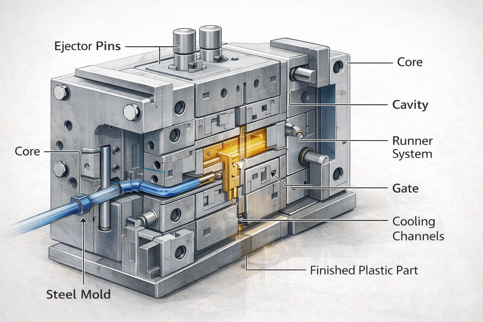
What is the difference between tooling and a mold?
The mold is one part of the tooling.
Tooling is the collective term for everything made specifically to produce a part: the mold itself, its base and frame, the ejection system, the cooling layout, any side actions, and the fixtures and gauges used in inspection. The mold is the cavity and core that form the part. When a supplier quotes tooling cost, the figure covers all of those elements rather than the block of steel alone, which is why two quotes for the same part can differ without either being wrong.
That distinction matters when comparing prices. A quotation that covers only a cavity and core may leave the buyer to pay for the frame, the hot runner or the gauges separately, and a quotation that includes automation features may be intended for a longer life than the programme needs.
What a bridge tool leaves out, on purpose
A bridge tool is designed to be adequate rather than optimal. It usually runs fewer cavities, which raises the part cost but lowers the tool cost. It may use standard mould bases and a simpler cooling layout, which lengthens the cycle. It may lack the automation that a production line needs, such as robot handling or automated part removal. And it is often built with a softer steel that will wear faster under abrasion from filled materials.
Those omissions are deliberate trade-offs. The point is to produce parts that are correct in geometry and material, not parts that are cheap per unit. Where the programme turns out to be short-lived, the bridge tool has done its job at a fraction of a production tool’s cost. Where it runs far longer than expected, it will wear and may eventually need replacing, which is the risk the buyer carries in exchange for the lower upfront spend.
When a bridge tool should be retired
The handover point is normally defined by volume or by a change in requirements rather than by the condition of the tool alone. If demand settles above the level the bridge tool can economically supply, the part price alone justifies the production tool. If the design changes in a way that affects the mold, such as an added feature or a different material, the change is usually made in the production tool rather than paid for twice.
Two habits make that handover clean. Keep the bridge tool’s processed parameters documented, because the production tool will be qualified against a known good part; and agree in advance who owns the bridge tool and what happens to it when the production tool arrives. Ownership and disposal are easy to settle at the start and awkward afterwards. Tooling practice for small manufacturers is described by the NIST Manufacturing Extension Partnership, and drawing conventions follow ASME standards.
Designing a part that survives both tools
A part will be molded in the bridge tool and later in the production tool, so the design has to work with both. That means keeping the nominal geometry identical between them and allowing for small differences in shrinkage behaviour, gating position and cooling, which affect warpage more than they affect overall size. Draft angles, wall thickness and rib proportions should be chosen so neither tool needs a compromise.
The features that cause the most trouble in handover are the ones with tight tolerances tied to gate or weld-line position, and cosmetic surfaces whose texture is applied to the mold. Both should be defined clearly enough that the second tool reproduces them without argument. Material references are published by ASM International, dimensional verification is described by the NIST Manufacturing Extension Partnership, and the low-volume alternative is set out under low volume injection molding.
Where the programme is regulated, the bridge tool also has to produce parts that can be documented. Inspection practice for the trial parts is described by the NIST Manufacturing Extension Partnership, and process waste obligations by US EPA rules.
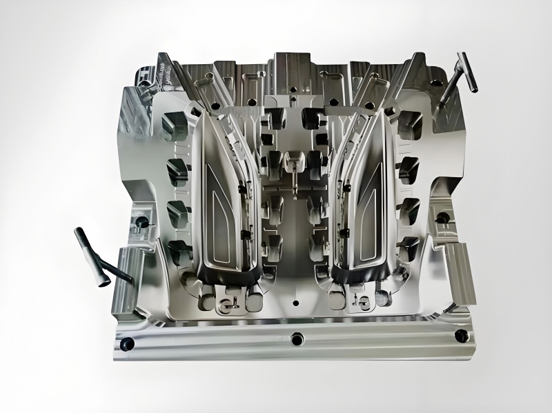
Send the part model with the volume you expect over the next twelve months, and request a bridge tooling quote alongside a production tool comparison.
FAQ
What is bridge tooling and when is it used in development?
A bridge tool is a mold built to produce real parts in the production material without the cost and lead time of a long-run tool. It is used for pilot builds, field or clinical trials, and early launches while demand is still uncertain.
What are the different types of tooling in injection molding?
Prototype tools validate geometry and fit, often in a substitute material; bridge tools produce production geometry in the production material for pilot quantities; and production tools are built for long-run volume, cycle time and automation.
Should a bridge tool be used instead of a production tool?
Use a bridge tool when the volume does not yet justify a production mold and parts are needed in the final material. Once demand settles, the per-part saving from a production tool usually repays its higher cost.