

Explore Injection Molding Materials, Defects & Validation
A thin fin at a housing seam may be harmless on one edge and unacceptable on the sealing land a few millimeters away. Calling both conditions minor flash hides the functional difference. The acceptance decision needs a location, a measurement direction and a defined part state before anyone selects a numerical limit.
Injection molding flash tolerance should describe permitted residual material on identified surfaces, rather than provide a general allowance for a tool that no longer closes correctly. Even an acceptable trimmed part can indicate a process or tooling issue that requires investigation. Product disposition and corrective action therefore need separate records.
This guide focuses on writing and verifying local acceptance requirements. It does not replace a defect investigation with a universal flash-height table. Resin, tool interface, feature access and assembly consequences determine which measurements actually matter.
Within the injection-molding process, agree the distinction between as-molded and finished acceptance. A drawing that implicitly permits hand trimming can create a different production route from one requiring acceptable parts directly from the tool. Record that difference before a trial becomes the baseline for repeat orders.
Where should injection molding flash tolerance apply?
Set limits by surface function and location.
Identify sealing, contact, sliding and visible zones separately, because the same residual fin can create leakage, assembly interference or cosmetic rejection depending on where it occurs on the part.
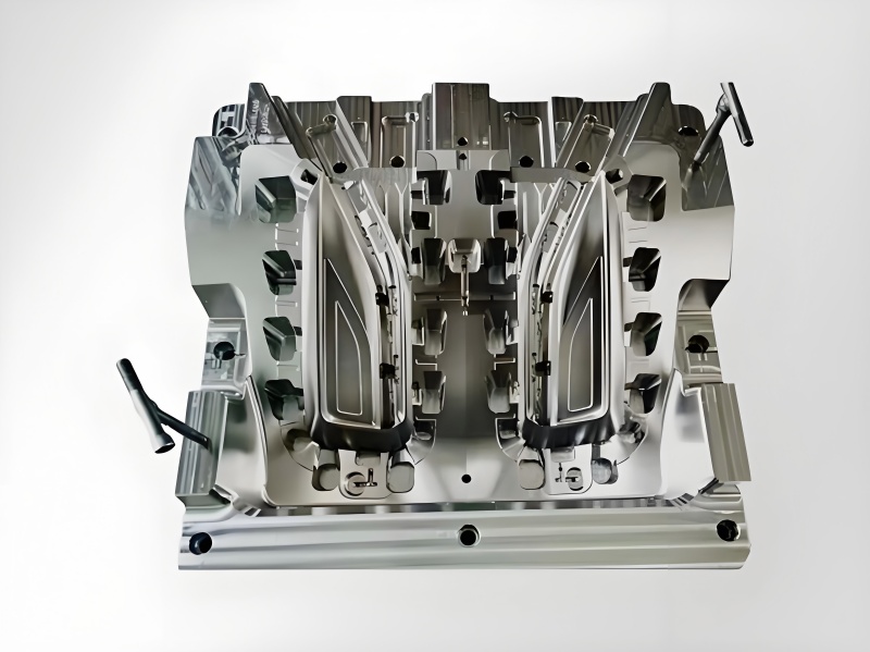
Mark the parting line, insert boundaries, slide interfaces and ejector locations on the model. Assign stable feature identifiers to the regions being assessed. A photograph with a circled defect helps communication, but a drawing location makes the requirement reproducible between shifts and laboratories.
Consider how the excess material behaves after assembly. A flexible fin may fold beneath a gasket or detach into a mechanism even if its free-state height appears small. Cosmetic boundaries also need a defined viewing method rather than a general instruction to make the seam invisible.
Autodesk's flashing guidance identifies parting-line and ejector-related excess material and distinguishes several possible causes. Use that context to locate the feature, while allowing the product’s actual function to determine acceptance. A limit on one external edge should not silently extend to a nearby functional land.
Measure thickness, height and extent separately
Thickness, height and affected length describe different aspects of flash. Thickness can describe the fin across its narrow section; height or projection describes how far it extends beyond the intended boundary. Define the local coordinate directions so two inspectors do not report different quantities under the same label.
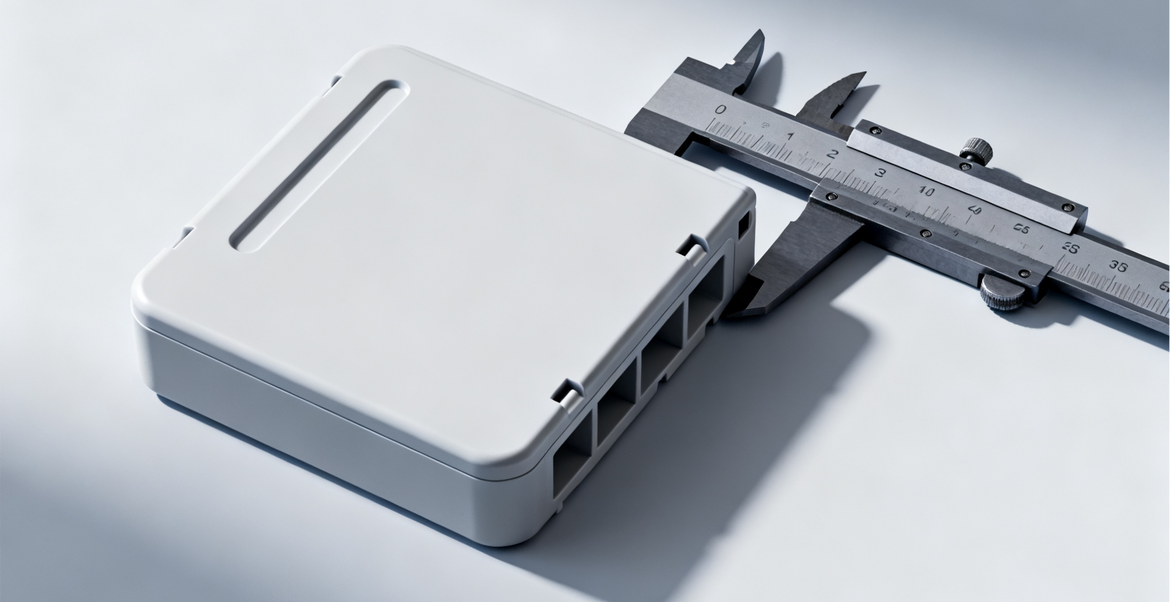
Choose a method that does not fold or compress the fin before its original condition is recorded. Mitutoyo's profile-projector information describes optical dimensional measurement; suitability for a particular flash feature still depends on orientation, edge visibility and resolution. Confirm the measurement method with representative parts before using it for disposition.
Measure the maximum relevant projection and its location, rather than averaging it into an apparently acceptable seam. If the feature varies along the boundary, record enough stations to describe the affected region and identify isolated spikes.
Preserve the as-received state in images and measurements. Trimming before inspection destroys evidence of the original condition. Where a destructive section is necessary to establish thickness, identify the sampled part and recognize that it cannot describe every unsectioned part automatically.
Separate allowed vestige from unwanted flash
A planned gate vestige, a parting-line offset and a flash fin require different requirements. A gate remnant is tied to an intentionally designed feed location; mismatch is a displacement between adjoining molded surfaces. Neither should become acceptable merely because a drawing contains a general flash allowance.
Define a permitted residual feature by its source, envelope and location. If a gate remnant is allowed inside a recess, state the envelope in that recess and keep the adjacent sealing or seating surface independently controlled. A general edge-break note is not an adequate substitute.
Likewise, distinguish a molded texture boundary from loose or detachable material. A cosmetic sample may show an expected seam without proving that every protrusion at that seam is acceptable. The master sample and drawing need compatible descriptions.
Use rapid-tooling review to resolve shutoff and parting-line decisions early. The review should identify which residual features are designed, which are allowed after finishing, and which indicate a nonconforming molding condition requiring investigation.
Document disposition and corrective action
Part disposition answers whether the identified components can be accepted, reworked or rejected. Corrective action answers why the unwanted material occurred and how recurrence will be controlled. Approval of one shipment after trimming does not establish permanent approval of the underlying condition.
Record affected cavities, dates, quantities, feature locations and the required post-rework checks. If a deviation is temporary, give it an expiry or a defined lot boundary. Otherwise, a contained trial exception can become an undocumented production specification.
Eastman's copolyester troubleshooting guide lists tooling fit, clamp behavior and process conditions among flashing considerations for its materials. Those categories help structure investigation, but its processing details must not be transferred unchanged to another resin.
Retain representative as-molded and finished parts when possible. Compare them to confirm that rework removed the obstruction without damaging the functional surface. Link the disposition record to the tooling or process change, and require a subsequent trial before closing the corrective action. A visually cleaner sample alone cannot demonstrate stable production.
A flash acceptance map for seals, sliders and seams
A useful acceptance table pairs each region with a quantity and a verification method. Enter the actual project limits after engineering review; copying generic numerical allowances can legalize material where the design has no clearance for it.
The following framework shows what needs agreement. Each row refers to a separate functional question, so passing one does not imply that the remaining conditions pass.
| Zone | Quantity or condition | Verification focus |
|---|---|---|
| Seal land | Specified residual envelope and damage | Local geometry and assembled sealing |
| Sliding edge | Projection and affected length | Travel clearance and debris |
| Visible seam | Defined appearance boundary | Agreed lighting and orientation |
| Trimmed boundary | Remaining material and parent-surface loss | Finished profile after rework |
Reference the feature identifiers, part state and measurement procedure on the drawing or controlled inspection plan. The standards and tolerances reference can support that discussion, while the released requirement supplies the actual acceptance values. Keep any temporary deviation outside the permanent drawing until its engineering consequences have been reviewed.
A molding trial that preserves the flash baseline
Begin a flash trial with a documented baseline rather than immediately changing several settings. Identify the resin grade and condition, tool and cavity, machine, cycle state and observed locations. Collect enough consecutive parts to distinguish a recurring feature from an isolated event.
Inspect tooling interfaces and review process records before deciding which hypothesis to test. Compare candidate changes under a controlled trial plan that preserves traceability between setting and part. A change that removes flash can also alter fill, packing or dimensional behavior elsewhere.
Keep startup parts separate from samples collected after the selected operating state is established. If the problem appears only after extended running, a short trial may miss the condition. The trial duration and sample selection should address the observed pattern.
Measure the original flash quantities at the same stations for each trial condition. Also record whether the material is attached, loose or removed during handling. Avoid judging improvement from photographs taken at different magnifications or orientations, and do not accept a process solely because the final few samples look better.
Checks after flash correction and trimming
A successful flash correction must preserve the rest of the part. Check the dimensions affected by process changes, the cosmetic boundary and the assembly functions that motivated the original limit. Trimming can solve interference while leaving gouges, a sharp edge or loose particles.
Where sealing matters, test the assembled interface under the product’s specified conditions. A local flash measurement is evidence about geometry, not a complete leak test. Where a latch or sliding interface matters, inspect its travel and engagement after the approved finishing route.
NIST's uncertainty guidance provides a basis for evaluating measurement contributions. For a small residual fin, orientation, edge interpretation and part deformation may matter alongside instrument performance. A display with additional decimal places does not establish adequate measurement capability.
Compare the chosen method with the decision boundary before using it to sort a lot. If inspectors cannot reliably distinguish acceptable from unacceptable conditions, improve the method or clarify the requirement. Repeatedly measuring the same ambiguous image does not resolve a poorly defined feature or viewing condition.
Releasing an as-molded or finished flash boundary
Release should connect an agreed feature limit with a demonstrated production and inspection route. Confirm the final part state, permitted finishing operations, approved sample references and checks after rework. Identify which changes in tool, resin or process require another review.
Preserve the evidence supporting the decision. NIST's traceability guidance explains that traceability belongs to measurement results and does not by itself establish fitness for purpose. For flash acceptance, retain the method, conditions and uncertainty needed to interpret the reported result, not only an instrument calibration label.
Resolve open questions such as inaccessible measurement stations, a cosmetic sample that conflicts with the drawing, or an allowed fin near a moving interface. These are release decisions with product consequences, not details to leave to a trimming operator.
For a pilot run, define the observations that will trigger additional tooling work. An approved temporary finishing route can be appropriate, but its labor, inspection burden and damage risks must be visible. Keep that commercial decision separate from claiming that the tool already produces the intended as-molded boundary.
FAQ
Can an approved sample replace a numerical flash requirement?
It can support appearance agreement, especially where viewing conditions are controlled, but it may not define a functional clearance or sealing boundary adequately. Pair the sample with identified regions, inspection conditions and any dimensional limits needed by assembly. Preserve the sample revision and condition. A worn or damaged master can shift the apparent acceptance boundary. Where sample and drawing conflict, resolve the conflict through the responsible engineering authority before using either to accept production.
Is all flash removal acceptable if the part still assembles?
Assembly is only one check. Removal can damage a sealing face, reduce a ligament, create a sharp edge or leave debris. Define the permitted finishing method and verify the resulting geometry and cleanliness against the product requirements. Keep the original nonconformance and rework disposition traceable. A part that fits once after uncontrolled trimming does not demonstrate that the finishing route is repeatable or that other functional surfaces remain acceptable.
Should a flash problem automatically stop every cavity?
The scope of containment should follow the evidence and product risk. Preserve cavity identity and compare the affected features before assuming either a common process issue or an isolated tooling problem. If traceability is missing, broader containment may be necessary because the affected population cannot be separated confidently. The disposition authority should define what may continue, what requires inspection and what must be held. A single clean cavity sample does not release an unidentified mixed lot.
Conclusion
A useful flash requirement identifies the surface, the residual geometry and the accepted final state. Measure projection, thickness and extent only where those quantities answer the functional question, then keep product disposition separate from the correction of tooling or process causes. Release depends on the finished part and a repeatable verification route.
Send 6CProto the model and drawing for a quotation, with critical seams, permitted vestiges and finishing restrictions marked. Include the proposed inspection method so acceptance can be considered before the tooling route is agreed.
{“@context”: “https://schema.org”, “@type”: “FAQPage”, “mainEntity”: [{“@type”: “Question”, “name”: “Can an approved sample replace a numerical flash requirement?”, “acceptedAnswer”: {“@type”: “Answer”, “text”: “It can support appearance agreement, especially where viewing conditions are controlled, but it may not define a functional clearance or sealing boundary adequately. Pair the sample with identified regions, inspection conditions and any dimensional limits needed by assembly. Preserve the sample revision and condition. A worn or damaged master can shift the apparent acceptance boundary. Where sample and drawing conflict, resolve the conflict through the responsible engineering authority before using either to accept production.”}}, {“@type”: “Question”, “name”: “Is all flash removal acceptable if the part still assembles?”, “acceptedAnswer”: {“@type”: “Answer”, “text”: “Assembly is only one check. Removal can damage a sealing face, reduce a ligament, create a sharp edge or leave debris. Define the permitted finishing method and verify the resulting geometry and cleanliness against the product requirements. Keep the original nonconformance and rework disposition traceable. A part that fits once after uncontrolled trimming does not demonstrate that the finishing route is repeatable or that other functional surfaces remain acceptable.”}}, {“@type”: “Question”, “name”: “Should a flash problem automatically stop every cavity?”, “acceptedAnswer”: {“@type”: “Answer”, “text”: “The scope of containment should follow the evidence and product risk. Preserve cavity identity and compare the affected features before assuming either a common process issue or an isolated tooling problem. If traceability is missing, broader containment may be necessary because the affected population cannot be separated confidently. The disposition authority should define what may continue, what requires inspection and what must be held. A single clean cavity sample does not release an unidentified mixed lot.”}}]}