

Molding design rules are not stylistic preferences; each one exists because a physical process will do something specific if it is ignored. The cost of ignoring them is not a slightly worse part, it is a tool modification that arrives after the tool has been cut.
The rules that matter most, and what each one prevents
Five checks carry most of the weight. Wall sections should be as uniform as the design allows, because thick regions cool more slowly, shrink more and produce sink marks and warp. Draft should be present on every face that runs parallel to the direction of mold opening, so the part releases without scuffing. Ribs should be thinner than the wall they stiffen, usually around half the thickness, so they cool at a similar rate. Bosses should be hollow with a thin wall rather than solid, for the same reason. And corners should carry a radius, which improves flow and reduces the stress concentration that causes cracking in service.
| Design element | Rule of thumb | Defect prevented |
|---|---|---|
| Nominal wall | Keep thickness uniform | Sink marks, warp, long cycle time |
| Draft angle | Add to all vertical faces | Scuffing and ejection damage |
| Rib thickness | Around half the adjacent wall | Sink marks opposite the rib |
| Boss wall | Thin wall with support ribs | Sink marks and internal voids |
| Corner radius | Radius where flow turns a corner | Stress cracking, poor fill |
What the A side and B side actually describe
Which half of the mold forms which face of the part.
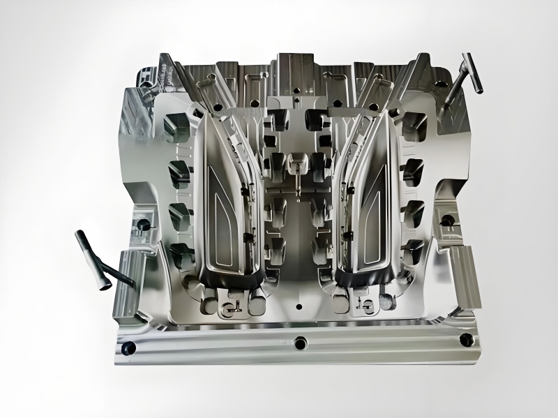
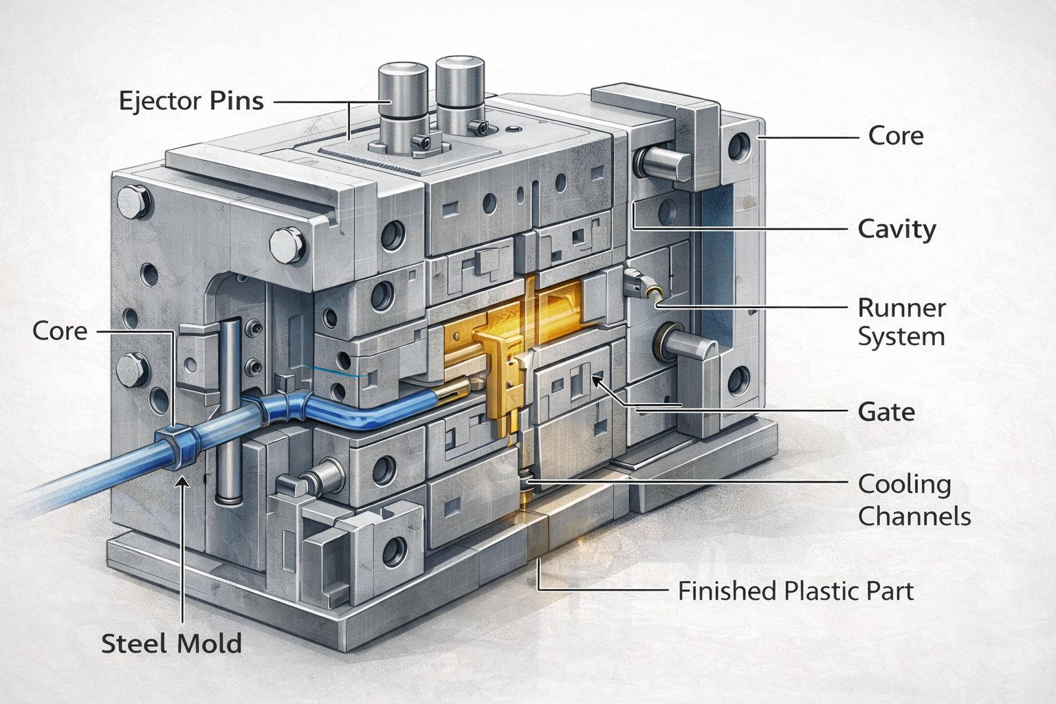
The A side is the cavity half, usually the visible or cosmetic face of the part. The B side is the core half, which typically carries the internal features — ribs, bosses, the ejection system and often the gate vestige. The distinction matters in design because the two faces have different quality expectations and different constraints: the A side is where texture and appearance are judged, and the B side is where structural detail is placed so it stays out of view.
Two design consequences follow. Where a cosmetic requirement conflicts with a structural feature, the feature belongs on the B side; and where the gate is positioned, its vestige will appear on the face that half forms, so gate location is a cosmetic decision as well as a filling one. Agreeing which face is which before the tool is designed prevents a late argument about where a weld line or gate mark is allowed to be.
What are the common failures caused by design
The recurring problems are predictable. Sink marks appear opposite thick features. Warp appears where shrinkage is uneven, often because wall thickness changes abruptly or because the part is asymmetrical in a way that distributes cooling unevenly. Short shots appear where a thin section is too far from the gate or where flow is obstructed. Weld lines appear where flow fronts meet, and they are weakest where the meeting angle is shallow. And ejection marks appear where a thin section is pushed out of the tool without enough support.
Most of these are reduced by the same three habits: uniform walls, generous radii where flow turns, and a gate position that fills the thick sections first and keeps weld lines away from load-carrying areas. Each habit costs nothing at the design stage and a tool modification later. Material shrinkage data is published by ASM International, and production practice guidance by the NIST Manufacturing Extension Partnership.
Features that add tooling cost
Three features routinely raise both tool cost and maintenance. Undercuts that cannot be formed by the parting line need slides or lifters, which add moving parts that wear and can flash. Deep, narrow features need high injection pressure and often steel that is difficult to cool. And a requirement for a very smooth or highly textured cosmetic face adds either polishing or etching work to the steel, which is expensive to reproduce if the cavity is later damaged.
The design response is to ask whether each feature is truly required. An undercut can sometimes be replaced by a snap-fit detail that forms in the direction of opening; a deep rib can sometimes be replaced by a shallower, wider one; a textured face can sometimes be limited to the surfaces people actually touch. Those substitutions preserve function while simplifying the tool, and they are cheapest to make before the design is frozen.
A checklist to apply before the tool is cut
Work through the drawing with these questions: is the wall thickness as uniform as it can be; does every vertical face have draft; are ribs and bosses thinner than the wall they meet; are corners radiused where flow turns; has the gate position been chosen with the cosmetic face in mind; is any weld line away from a load path; and are there features that need a slide or lifter, and could they be redesigned. Answering them takes an afternoon and prevents the change orders that otherwise arrive weeks later.
It is also worth confirming the material before the review, because shrinkage, viscosity and filler content all change which issues matter. A glass-filled grade wears the tool faster and flows differently from an unfilled one, so the same geometry may behave in two ways. Drawing conventions for these callouts follow ASME standards, the low-volume alternative is described under low volume injection molding and low volume manufacturing, and process handling obligations are set out by the US EPA.
Tooling design guidance for the elements these rules depend on is published by the NIST Manufacturing Extension Partnership.
Send the model with the cosmetic face identified and the material specified, and request a design review against these rules before tooling is committed.
FAQ
What are the main design guidelines for injection moulding?
Uniform wall thickness, draft on faces parallel to the opening direction, ribs and bosses thinner than the adjacent wall, radii where flow turns, and a gate position chosen with the cosmetic face in mind. Each addresses a specific defect rather than a preference.
What is the difference between the A and B sides of an injection mold?
The A side is the cavity half, which usually forms the visible face of the part, while the B side is the core half, which carries internal features such as ribs, bosses and the ejection system. Cosmetic and structural requirements are split accordingly.
Which design features add the most tooling cost?
Undercuts needing slides or lifters, deep narrow features that require high pressure and are difficult to cool, and demanding cosmetic surfaces that need polishing or etching. Each can often be redesigned to simpler geometry without losing function.