

Extrusion printing is often dismissed as the hobby process, and then specified anyway when the part is 600 mm long, has to sit in a paint oven, or needs to be replaced by lunchtime tomorrow. Industrial FDM solves a specific class of problem: large single-piece parts, high-temperature thermoplastics, tooling that must survive shop-floor handling, and fixtures that are cheaper printed than machined. This guide covers what the process is actually used for in production environments, how material choice follows the application, what drives cost and lead time, and how to specify inspection on a printed part that carries a load.
What is industrial FDM used for?
Large parts, hot environments, and shop-floor tooling.
Extrusion printing suits jigs, fixtures, covers, ducts and brackets where size, heat tolerance or turnaround matters more than fine detail.
The process lays down a thermoplastic filament layer by layer, which gives it two characteristics that decide where it fits. The first is size: parts can be built in one piece at dimensions that resin and powder-bed processes cannot reach, avoiding the joints and fasteners that a split design would need. The second is material range, including engineering thermoplastics that hold shape at temperatures where resin would soften. The terminology used for the process and its variants follows the additive manufacturing vocabulary maintained in ASTM F2792.
In production environments that translates into a consistent set of applications. Assembly fixtures and check gauges that would otherwise be machined from aluminium. End-of-arm tooling for robots, where a lightweight printed gripper reduces the payload the arm has to carry. Covers, ducts and enclosures for equipment where the part is large and the surface does not need to be cosmetic. And functional prototypes where the geometry is too big for another process.
The process is less suited to small, finely detailed parts, to anything with a cosmetic gloss requirement, and to applications where strength across layer boundaries is the governing load case. Recognising those limits early is what keeps FDM in the role it performs well.
Which thermoplastics make sense, and when?
Match the polymer to temperature and load, not to habit.
ABS and PETG cover general parts, polycarbonate adds strength and heat tolerance, nylon adds toughness and wear resistance, and PEI handles the highest service temperatures in this family.
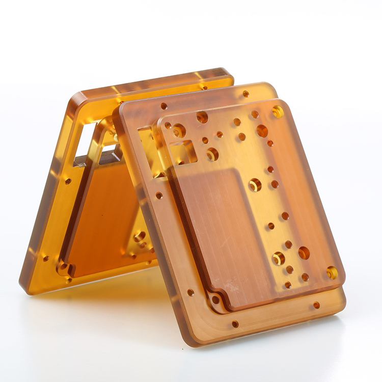
Material choice in extrusion printing is driven by the environment the part will see. General-purpose parts for indoor use are usually specified in ABS or PETG, both of which print predictably and accept finishing. Where the part needs more stiffness and heat resistance, polycarbonate moves the ceiling up. Where the requirement is toughness, wear resistance or repeated flexing, nylon is the usual answer. And where the part sits close to heat, for example in a fixture near a curing oven or an engine bay, PEI takes the highest service temperatures in the family.
Two practical constraints accompany the choice. Higher-temperature polymers require a heated build environment to control warping, which affects how large a part can be printed in them. And every material change alters the surface finish, the dimensional behaviour and the finishing options, so a material substitution late in a program is a change to the part rather than a swap of consumables.
6CProto lists the grades available for printing on the material pages, including PEI, polycarbonate and ABS.
| Material | Why it is chosen | Typical parts |
|---|---|---|
| ABS | General-purpose, predictable finishing | Housings, covers, brackets, mock-ups |
| PETG | Toughness with easier printing behaviour | Enclosures, jigs, parts needing some flex |
| Polycarbonate | Stiffness and higher heat tolerance | Fixtures, structural covers, tooling |
| Nylon | Impact and wear resistance | Gears, wear pads, snap features |
| PEI | High service temperature, dimensional stability | Parts near ovens, hot ducts, aerospace tooling |
How large can a single part be, and when should it be split?
Large enough to avoid joints, with some planning.
Printed parts are produced well beyond the size of resin or powder-bed builds, and a design that exceeds the envelope is divided along load paths.
Size is one of the reasons to choose extrusion printing, so it is worth understanding where the practical limits sit. The build envelope defines the maximum dimensions, but the material affects how much of that envelope can be used: polymers that warp easily need more thermal control, and a tall part has more time to accumulate distortion as it prints.
Where a part must be split, the design work is in choosing where. Joints should fall in low-stress regions rather than at the point of maximum bending, they should be designed with an overlap or a lap rather than a butt joint, and the fastening method should be part of the original design rather than added afterwards. A split that follows the load path and includes alignment features will behave like one component; a split chosen for convenience will not.
Orientation interacts with size as well. A large flat panel printed flat on the platform has the least distortion but occupies the full footprint, while the same panel printed vertically is more compact in the bed but shows more layer directionality in its surface. Both options are legitimate; the choice follows what the part must do.
How do layer height, tolerance and surface finish relate?
Layer height trades print time against surface quality.
A finer layer produces a smoother surface and more accurate detail at the cost of machine time, while a coarser layer prints faster and leaves visible stepping on angled faces.
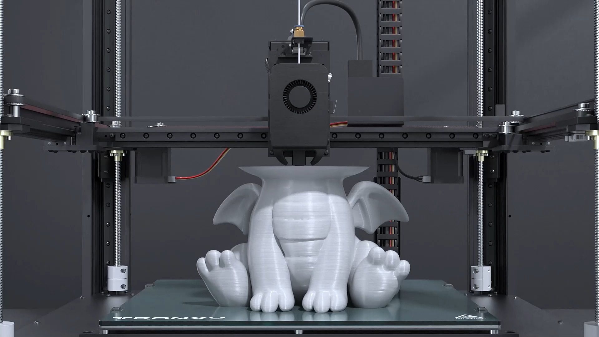
The visible layer lines in extrusion printing are a function of layer height and geometry. Horizontal surfaces print smooth, vertical walls show the layer edges, and angled faces show stepping that becomes more pronounced as the angle moves away from vertical. Reducing the layer height reduces that stepping and improves the resolution of small features, but it increases the number of passes and therefore the print time, which is the largest element of cost.
Tolerance behaves differently. The dimensions controlled directly by the machine, such as wall position in the horizontal plane, are more predictable than the vertical dimension, where each layer adds a small amount of variation. Holes print slightly undersized because the extruded path curves inward at the top of an arc, which is why functional holes are often drilled to final size rather than printed to it.
Where a face has a requirement, machining it after printing is usually more economical than printing it finely. The framework for those callouts is set out on 6CProto’s standards and tolerances page, and confirming the achievable range for a specific feature before the design is frozen saves a reprint.
How do orientation and anisotropy affect a printed part?
Parts are strongest in the plane of the layers.
Extrusion bonds each layer to the previous one, so a load that pulls layers apart is the weakest loading direction, and orientation is chosen to keep the highest stress inside a layer.
Anisotropy is the single most important mechanical characteristic of an extrusion-printed part. The practical summary is that the bond between layers is weaker than the material within a layer, so a bracket printed standing up can fail along a layer boundary under a load that the same bracket would carry easily when printed flat.
That has two consequences for specification. The first is that the load case has to be communicated, because orientation is a decision made by the shop and it changes the result. The second is that features under load, such as a boss that takes a screw or a rib that carries bending, should be designed so their stress does not cross layer planes where it can be avoided.
Where the load is genuinely severe, the answer may be a different process rather than a different orientation. A machined or molded part has isotropic behaviour that printing cannot match, and recognising when that matters is part of the design conversation. The measurement methods used to compare printed and conventionally made parts are described in the NIST additive manufacturing program.
What drives the cost of an FDM part?
Machine time, material, supports and finishing.
Print time is the largest input and it scales with part volume, layer count and the amount of support material, so design decisions that reduce height or support volume reduce price directly.
Print time dominates because the machine lays material down at a fixed rate, so a part that occupies more volume or more layers takes longer to build. Support structures add both material and time, and they are needed wherever the geometry overhangs beyond what the printer can bridge, which makes overhang reduction one of the most effective cost levers in a printed design.
Material cost is usually secondary, except where an engineering thermoplastic is required: PEI or polycarbonate costs more per kilogram than ABS and requires a controlled build environment, which adds to the price of the part.
Post-processing is the third input. Support removal is manual, sanding and finishing add labour, and any machined face adds a setup. As with other processes, specifying finishing per surface rather than across the whole part keeps the cost where the value is. Requests submitted through the quote flow are reviewed for manufacturability before production, so orientation and support decisions are visible before the build starts.
Why is extrusion printing used for fixtures and tooling?
Because a printed fixture can be replaced in a day.
Jigs, gauges, assembly aids and end-of-arm tooling are usually low-volume, geometry-specific and needed quickly, which is exactly the combination that makes printing cheaper than machining.
A machined aluminium fixture takes programming, stock preparation and machine time, and it is justified when the fixture will last for years. A printed fixture does the same job for a fraction of the lead time, and where it wears out it can be reprinted from the same file. That economics favours printing for anything that is design-specific, temporary, or likely to change between product revisions.
End-of-arm tooling adds a second argument: weight. A printed gripper or mounting bracket reduces the mass the robot has to accelerate, which can allow a faster cycle or a smaller arm. Where the tooling carries a real load, orientation matters and the load case should be part of the request.
Fixtures also tend to be large, which suits the process. A single printed assembly aid that spans a work cell is practical in extrusion printing and would be expensive in most other additive routes. The wider engineering context for industrial additive production is summarised on the ASME additive manufacturing topic page.
How should a printed part be inspected?
Check the interfaces, the fit and the function.
Dimensional inspection covers the features that locate or mate, while appearance is judged against a defined condition and functional checks confirm that the part does its job.
The features worth measuring on an extrusion-printed part are the ones that interact with something else: mounting holes, locating faces, and any dimension that decides whether the assembly closes. Vertical dimensions carry more variation than horizontal ones, so a callout in the build direction deserves attention during review.
Appearance should be judged under a stated viewing condition, because layer lines read very differently under direct light and diffuse light. Where the part is a fixture rather than a product, appearance usually does not matter at all, and saying so removes an unnecessary finishing step.
Functional checks complete the picture: does the fixture hold the part, does the gripper grip, does the cover close. Where a program needs third-party verification rather than an internal record, certification bodies such as UL publish their additive manufacturing service scope. 6CProto provides quality inspection reports on request and assigns a dedicated project manager to each order, so the scope of inspection can be agreed before production rather than after delivery.
Specifying a large or high-temperature part
Extrusion printing performs best when the requirement is size, temperature or turnaround, and when the design uses the process rather than fighting it. Large fixtures, ducts, covers, tooling and low-volume production parts all fit that pattern, and the material choice follows the service environment rather than preference. Where fine detail, a glossy surface or isotropic strength is the governing requirement, another process will serve the part better.
The specification that gets a good result is short. State the load case and the service temperature, so the material and orientation can be matched to them. Say which faces must be accurate and which may be left as-printed. Identify the interfaces that must fit. And say whether the part will be ordered again, because a repeat order is only a repeat if the material, orientation and finishing route are recorded. The additive manufacturing vocabulary behind those notes follows the standards work coordinated through ASTM committee F42.
FAQ
How expensive is FDM printing?
Price is dominated by print time, which scales with part volume, layer height and support material. A large part with modest detail can cost less than a small part printed at fine resolution, because the machine spends its time laying material rather than travelling. Material cost becomes significant only when an engineering thermoplastic is required. Post-processing, including support removal and any machined face, is priced as labour and is worth specifying per surface.
Can large parts be printed in one piece?
Often yes, and that is one of the main reasons to choose the process. Where a design exceeds the available build envelope, or where the material’s warping behaviour makes a very tall part impractical, the part is divided along load paths rather than at convenient geometry. Joints should fall in low-stress regions and include alignment features, so the assembled part behaves like one component instead of two pieces held together.
Which materials handle heat best?
Within the thermoplastics used for extrusion printing, PEI offers the highest service temperature, with polycarbonate and nylon above the general-purpose materials. High-temperature polymers require a controlled build environment to manage warping and layer bonding, which affects how large a part can be produced in them. Where a part will sit close to heat, state the service temperature in the request so the material and build environment can be matched to it.
Do printed fixtures last long enough to be worth making?
For low-volume production, prototyping and design-specific tooling, they usually do, and the economics are strong: a fixture can be printed and delivered in a fraction of the time a machined equivalent takes. Wear life depends on the material and the contact loads, and a fixture that sees abrasive contact or high clamp forces may be better in aluminium. Where the fixture is likely to change with the product, printing also means the next revision is a file update rather than a new machining setup.
If a part is too large, too hot or too urgent for another process, send the model with the service temperature and the load case. 6CProto reviews extrusion printing projects for manufacturability, matches orientation and material to the application, and returns a DFM report with the quote. Upload the file at the 6CProto quote page or send it to projects@6cproto.com.