

PTFE machines nothing like metal. The material is soft, slippery, and dimensionally unstable under heat, so a tool that works beautifully on aluminum will smear, fuzz, or melt the edge of a PTFE part — and the finished dimension will drift when the part warms up. Engineers who quote PTFE parts from metal habits usually get either fuzzy edges or a part that does not hold its tolerance in service. The fix is to understand the material’s behavior and design the part and the process around it, not to treat PTFE as “soft aluminum.”
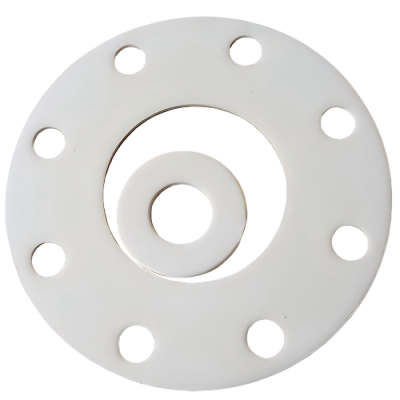
PTFE properties that complicate machining
Three properties drive every machining decision. PTFE is soft, so cutting edges must be sharp and the toolpath must avoid rubbing that smears the surface. It has a high coefficient of thermal expansion, so local heat from cutting changes the dimension during the cut and in service. And it is slippery, which sounds helpful but means the material deflects instead of cutting cleanly and chips can be difficult to control. The result is a material where feed, speed, tool geometry, and temperature control matter more than they do for many metals.
PTFE also moves after machining. Because it expands and contracts with temperature, a part machined to size in a warm shop can be undersized in a cold one. If the drawing ignores the service temperature, the inspection dimension and the installed dimension will disagree.
Tooling and cutting parameters that reduce fuzz and melting
Sharp, polished tools with positive rake angles are the first requirement; a dull edge rubs and generates heat that melts or fuzzes the surface. Keep the tool geometry simple and the cut continuous where possible, use moderate speeds with controlled feed so the tool actually shears the material, and support thin features so they do not deflect. Coolant is used selectively: PTFE conducts heat poorly, and flood coolant can help control temperature, but the material must be dry before measurement because it absorbs little moisture yet carries coolant into the inspection.
Pecking and chip control matter on deep features. Long, stringy PTFE chips can wrap tools and pull the material; sharp tools that produce small chips, and toolpaths that clear chips regularly, prevent the built-up heat that causes dimensional drift. The practical result of good parameters is a clean edge and a dimension that stays stable through the inspection temperature.
Achievable tolerances and why they differ from metals
PTFE cannot hold metal tolerances across a range of temperatures, and the drawing should say so. A machined PTFE feature can be held to a practical tolerance at the measurement temperature, but the same feature will move with thermal expansion and with the relaxation of machined-in stress. Tight tolerances on large or thin PTFE features are often better achieved by designing the mating fit with clearance and using a seal or gasket, rather than by asking the machinist to hold a metal-class number on a material that will not stay there.
| Feature type | Practical approach | Why |
|---|---|---|
| Outside diameter / bore | Moderate tolerance at stated temperature | High thermal expansion moves the dimension |
| Thin wall or long feature | Support during machining; larger tolerance | Material deflects and relaxes |
| Sealing surface | Sharp tool, controlled finish, flat reference | Fuzz and waviness defeat seals |
| Threads | Machined or tapped with PTFE-specific practice | Soft threads deform; inserts often better |
State the measurement temperature on the drawing or in the inspection note. Without it, the shop measures at 20 °C and the buyer measures at 25 °C, and neither number is wrong — which is exactly the argument a tolerance note prevents.
Design workarounds: features, thickness, and sealing
Design PTFE parts around the material instead of forcing metal geometry onto it. Avoid sharp internal corners that concentrate stress in a soft, creep-prone material; keep wall thickness as uniform as practical; and prefer geometry that can be machined with sharp, supported tools. Where a seal is required, use a groove geometry with a controlled squeeze and a gasket or O-ring that the PTFE part simply retains, rather than expecting a bare PTFE surface to seal by metal-style interference.
Threads deserve special attention. Threads cut directly into PTFE are soft and strip easily; where a threaded joint is functional, plan for threaded metal inserts, or design the PTFE as a seal or guide around a metal fastener. The material page on this site defines the PTFE grades available; the machining decisions above are what turn the grade into a working part.
Finishing and cleaning PTFE parts safely
PTFE parts need little finishing when the cutting parameters are right, and aggressive finishing can do more harm than good. Deburr with a sharp blade or controlled process rather than tumbling that rounds functional edges; avoid abrasive blasting that embeds media in a soft surface. Clean with solvents compatible with PTFE and the application, and dry thoroughly before measurement or packaging, because the material’s low friction makes handling easy but its sensitivity to contamination matters in sealing and cleanroom uses.
Document the cleaning and packaging if the part is for a clean or chemical process; a PTFE part with embedded debris defeats the purpose of choosing PTFE in the first place. The CNC team can confirm the practical tolerance and finish on your geometry before quoting, and the material pages list the grades and stock forms available for machining.
A sealing example shows where the design rules pay. A PTFE insulator must seal around a metal stud while holding a light axial load. The engineer who designs it like a metal part specifies a tight bore tolerance and a flat sealing face, expecting the PTFE to seal by interference. The machinist warns that the bore will move with temperature and that a bare PTFE face will not seal reliably by metal-style squeeze; the redesign adds a small groove for an O-ring, relaxes the bore tolerance to a practical range, and lets the PTFE act as the retainer and the O-ring act as the seal. The part costs less to machine because the tolerance is realistic, it seals consistently across the temperature range, and it survives assembly without cracking a sharp corner. The same logic applies to a thin-wall guide: instead of specifying a metal-class wall tolerance that the material cannot hold, the designer adds a boss or a rib where stiffness matters and leaves the unsupported span to a practical tolerance. When the drawing states the service temperature, the measurement temperature, and the functional surfaces, the shop can quote the process that holds the dimensions that matter and stop fighting the ones that do not. That is the difference between machining PTFE as a plastic and machining it as a metal: the material’s behavior is treated as the design input, and the drawing is written around it rather than against it.
Before quoting a PTFE part, confirm the service temperature and the measurement temperature, mark the functional surfaces, and decide whether tight features should be machined, sealed by a separate element, or relaxed to a practical tolerance. Confirm the grade and the stock form with the material supplier, and state the cleaning and packaging requirement if the part serves a clean or chemical process. The drawing that carries these notes is the one a shop can quote with confidence — and the part that comes back is the one that fits at the temperature where it works.
Frequently asked questions
Can PTFE be machined to the same tolerance as aluminum?
Not over a temperature range. At a single measurement temperature a skilled shop can hold a practical tolerance, but PTFE’s thermal expansion is far higher than aluminum’s, so the part moves with temperature and with stress relaxation. Specify the tolerance at a stated temperature, or design the fit to absorb the movement.
Why do PTFE edges come out fuzzy?
Fuzz comes from dull tools and rubbing cuts that tear the soft material instead of shearing it. Sharp, polished tools with positive rake and controlled feed produce clean edges; once the surface is fuzzed, removing it without damaging the geometry is difficult, so the fix belongs in the cutting parameters, not in post-processing.
Is filled PTFE easier to machine than unfilled?
Filled grades such as glass-filled or carbon-filled PTFE machine more like a rigid material and hold dimensions better, but the fillers wear tools faster and change the material’s chemical and friction properties. Choose the filled grade for the application requirement, not for machinability alone, and confirm the grade with the material supplier.
The short version for quoting
Send the drawing with the service temperature, the functional surfaces, and the tolerance basis stated, and let the shop quote PTFE with the process it needs: sharp tools, controlled temperature, and inspection at a defined condition. A PTFE part specified like a plastic rather than like a metal is a part that seals, fits, and lasts.

If you are specifying a machined PTFE component, the 6CProto machining team can review the geometry and tolerance basis before quoting, so the part is designed for the material instead of against it.