

A tighter cutting program cannot guarantee that a PTFE part holds the same size under every measurement and assembly condition. A bore can be affected by temperature, restraint, and sustained loading after the tool has left it. PTFE CNC machining therefore starts with a defined dimensional state and a fit strategy, not a universal tolerance promise.
Why PTFE moves after machining
For PTFE CNC machining, define the material grade, free or restrained inspection state, temperature conditions, supported workholding, tooling, and functional fit. Separate thermal movement, clamping deformation, and time-dependent change under load. Compare geometry and process alternatives against the actual assembly requirement rather than trying to solve every dimensional risk with a tighter drawing tolerance.
First identify what changed and when. A size shift after unclamping suggests a different investigation from a shift after a temperature change or prolonged compression. The sequence helps distinguish possible causes without assuming all movement is residual stress or all dimensional error is a machining mistake.
Ensinger’s sealing-application discussion highlights material selection where creep matters. Chemical resistance and low friction do not establish that a PTFE feature will retain its loaded geometry. Assess the actual grade, stress, temperature, and exposure time for the application.
Fixturing and sharp-tool needs
Compare two workholding proposals by the condition they create in the material. Stronger clamping may prevent movement during cutting while distorting the feature being finished. Distributed support and appropriate locating surfaces can be more useful than simply increasing holding force.
Mitsubishi Chemical Group’s plastics-machining guide explains why polymer cutting differs from metal cutting, including elasticity and heat behavior. Ask how the proposed tooling, support, and chip removal address the actual PTFE geometry. Sharp suitable tools are part of that plan, but they cannot compensate for an undefined acceptance state.
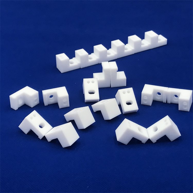
Identify thin lips, slender walls, holes near edges, and unsupported spans. For these features, agree the released condition and how measurement will avoid introducing a significant deformation of its own. A reading taken under a heavy contact force can be repeatable yet unrepresentative of the required free-state dimension.
Tolerance strategies
Define a tolerance only after relating it to the fit and the measurement condition. NIST’s dimensional-metrology FAQ discusses temperature effects in dimensional measurement. The relevant coefficient must match the actual material and temperature range; a convenient generic constant is not an acceptance specification.
For an illustrative sensitivity check only, assume a 50 mm feature, a constant expansion coefficient of 100 × 10⁻⁶/K, and a 10 K temperature change. The linear estimate ΔL = αLΔT gives 0.05 mm. The coefficient is an assumed calculation input, not a measured value or a specification for any supplied PTFE grade.
This estimate considers thermal expansion only. It omits restraint, non-linear material behavior, loading, and time-dependent effects. Use actual supplier data and a suitable design analysis for the part. Do not subtract this hypothetical allowance from every drawing dimension or treat it as proof that a proposed fit works.
Table: design alternatives
Compare alternatives by their effect on function and acceptance. A local interface change or more suitable stock form may resolve a problem that another decimal place on the drawing cannot. Any material or geometry change still needs approval against the operating requirements.
| Problem | Candidate review | What remains to validate |
|---|---|---|
| Thin unsupported section | Increase local support or revise the section | Released geometry and assembly function |
| Fit changes with temperature | Review clearance, material data, and mating-part response | Fit across the required operating conditions |
| Loaded feature changes over time | Review stress, support, and a suitable grade or design alternative | Time-dependent assembly behavior |
| Measurement deforms the part | Agree contact force, support, and suitable method | Correlation with the defined acceptance state |
| Excessive stock removal | Compare closer stock sizes or a suitable near-net blank | Stock consistency and finishing allowance |
Keep the required output visible. A seal, guide, spacer, and electrical insulator can have different priorities even when their nominal dimensions are similar.
When molding or stock shapes win
Compare rod, tube, and plate with a suitable molded or sintered blank as the geometry and supply route allow. Ask what preparation, finishing allowance, and inspection each option requires. An alternative starting form may reduce material removal without eliminating the need to control the critical interface.
Ensinger’s semi-finished-plastics machining guide discusses stock processing, dimensional stability, and machining considerations. Use material-specific advice when agreeing the route. PTFE should not be assigned the same molding assumptions used for an unrelated melt-processable plastic.
For a development order, machining may provide flexibility while the fit is resolved. For repeated geometry, a closer blank may deserve comparison. Evaluate the complete accepted component, including any required material evidence, stabilization, cleaning, and final inspection. Confirm the actual offered blank process with the supplier.
FAQ
These questions address specification details that should be settled before sample approval.
Will machining PTFE more tightly prevent later size changes?
No. A tighter as-machined dimension does not remove thermal movement, restraint effects, or time-dependent deformation under load. Define the required inspection and service conditions, choose a suitable design and grade, and validate the relevant fit or function.
Can a generic thermal-expansion coefficient set the final tolerance?
No. Use data applicable to the exact grade, temperature range, and required analysis. A constant-coefficient calculation can illustrate sensitivity, but it may omit non-linear behavior, restraint, loading, and time-dependent effects. Keep illustrative inputs separate from the procurement specification.
Does a free-state inspection prove that a PTFE seal will work?
No. It establishes only the measured characteristics in the defined condition. Seal function also depends on assembly geometry, loading, temperature, media, and time. Specify the dimensional acceptance separately from the application validation and agree who supplies each form of evidence.
Related process selection notes
Choose inspection and process controls together. ASME Y14.5 provides geometric communication rules under the selected drawing convention. Define functional relationships and the required measurement state so the supplier can propose an appropriate method.
Review the project’s requirements through the standards and tolerances discussion. A general machining tolerance is not enough to specify the performance of a soft, temperature-sensitive component. Mark the dimensions that determine acceptance and distinguish them from reference or noncritical geometry.
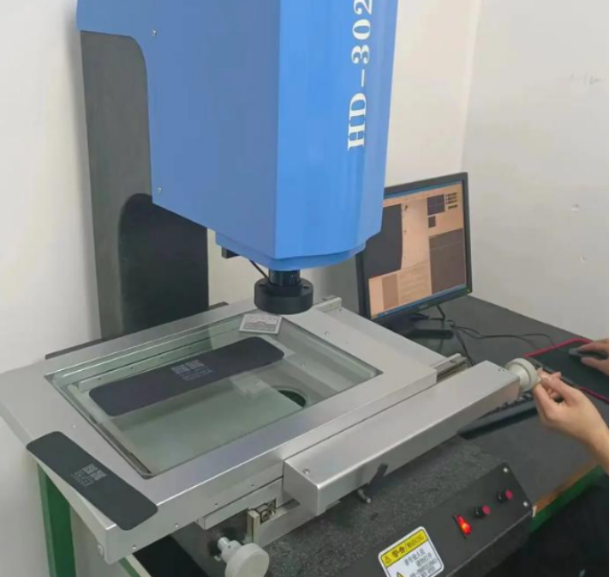
Approve a representative sample in the stated condition. If assembly loading or exposure determines function, include that evaluation in the design validation plan. A passing free-state dimensional report remains useful evidence, but it does not establish the loaded fit over the intended service period.
Internal links and next steps
Send the exact PTFE grade or approved specification, CAD, drawing, quantity, stock restrictions, critical fits, and required inspection conditions. Include mating-part details and relevant load, temperature, time, and exposure information. Identify the evidence needed for material and finished-part acceptance.
Use the PTFE material review and CNC machining discussion to settle the proposed stock and manufacturing route. Ask the quotation to state limitations, assumptions, and any requested design changes.
Request a 6CProto PTFE machining review with the fit and inspection state defined. Resolve the conditions behind the dimension before approving a tolerance or a production sample.