

An optical mount that drifts a few micrometers with temperature can turn a perfectly aligned bench into a failed experiment, and the drift is often designed in: the mount mixes aluminum and steel without considering thermal expansion, the adjuster threads gall, or the datum face relaxes after machining. Optomechanical hardware is precision mechanics with a thermal and stability budget — the material, the datum features, and the adjuster design decide whether the alignment holds. Machining the mount is the last step of an engineering process that starts with the stability requirement, not with the CAD file.
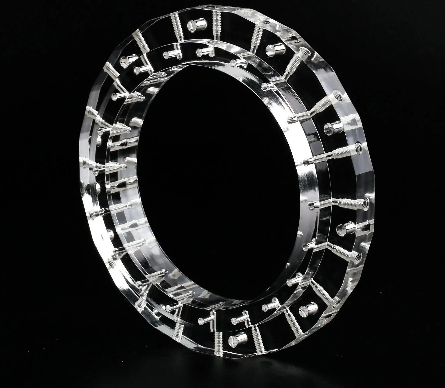
Optical mount functions that drive machining strategy
Optical mounts locate, align, and hold optics against vibration and temperature change. The functions drive the machining: locating faces must be flat and square to the optical axis; bores and counterbores hold lenses or mirrors at controlled depths; adjuster features convert screw motion into fine angular or linear movement; and mounting holes tie the assembly to the breadboard or the instrument frame. Each function has a tolerance and a surface requirement, and the machining strategy follows the function: datum faces are machined in the same setup where possible, and critical features reference the same datum scheme so the assembly aligns without shimming.
The drawing should name which surfaces are optical datums and which are reference only. A mount with two datums competing for the same alignment will not hold position, no matter how precisely each is machined.
Materials and stability: aluminum, stainless, and invar options
Material choice sets the thermal budget. Aluminum is light, machines well, and is the default for benches and mounts where its expansion is acceptable; stainless is denser and stiffer with lower expansion than aluminum; invar and other low-expansion alloys appear where the alignment must hold across temperature. The mount material should be matched to the optics and the housing it sits in, because differential expansion between the mount and the structure it is bolted to is what moves the alignment. The material data — coefficient of expansion, stiffness, and stability after machining — belongs in the design review, not in the shop’s default choice.
Stability also comes from the material condition: a stress-relieved or aged stock holds machined geometry better than stock with high residual stress, and thin mount features can move after machining if the material was not stable to begin with. State the material condition on the drawing when the mount is precision-critical.
Datum and kinematic-feature machining
Optical mounts often use kinematic or semi-kinematic features — balls in V-grooves, flat-and-cone seats, or precision pins — to locate components repeatably. Machining these features requires datums that are measurable and that match the assembly’s constraint scheme: the primary datum should be the face that carries the load, the secondary datum the edge that locates it, and the features should be machined in the same setup so their relationship is controlled by the machine rather than by the fixture. A kinematic mount is only as repeatable as the datum scheme it is machined to.
Coordinate measurement is the inspection method for these features: the position, the perpendicularity, and the relationship between the datums and the kinematic seats should be verified against the assembly constraint, not just against individual dimensions. The inspection report should state the datum scheme it measured to, so the shop and the assembly engineer are speaking the same language.
Threads and adjuster features for alignment hardware
Adjuster threads are where mounts fail in use. A fine-pitch thread that gall in aluminum, an adjuster screw that binds against an untapped hole, or a thread with too much play makes fine alignment impossible. The design choices are the thread size and pitch, the material pair, the lubricant, and the seating feature: a ball end or a conical seat turns a screw into a stable adjuster, while a flat-ended screw on a flat surface can walk and drift. The adjuster features should be machined with the clearance and the surface finish that the motion needs, and the drawing should state the adjustment travel and the torque or force the mechanism must tolerate.
Threads in aluminum mounts benefit from inserts where the adjuster is cycled often, and the insert choice — brass, stainless, or a helically coiled insert — should match the load and the environment. The threading and inspection practices on this site apply directly to these small, precision features.
Finishing effects on reflectivity and stability
Finishing an optical mount is a functional decision. Black anodizing reduces stray light and is standard on aluminum mounts; the coating changes dimensions slightly and should be planned on fits. Bare or plated surfaces appear where electrical contact or low outgassing matters, and the finish must not distort the datum features. The finish decision should be made with the optical designer, because a reflective face near the beam path, a mounting face that must stay flat after coating, and a thread that must hold its class after anodizing are all affected by the coating process.
Document the finish on the drawing with the coating thickness and the measurement basis, and confirm the anodizer’s process on the actual alloy. The precision machining and surface finishing teams on this site cover the capability; the stability and alignment requirements above are what make the mount work in the instrument.
How the alignment requirement reaches the drawing
A mount design example shows how the requirements flow to the drawing. An instrument needs a mirror mount that holds an optic and allows fine angular adjustment, with the alignment holding across a temperature change. The design review starts from the stability budget: the mount material is chosen so its expansion matches the housing, the datum face is machined flat and square to the optical axis, and the adjuster uses a fine-pitch screw against a ball seat to avoid the walking that a flat-ended screw would cause. The drawing marks the datum face, the bore that locates the optic, and the adjuster features, and the inspection plan measures the bore position and the datum squareness rather than every dimension on the part. The machining is done in one setup for the datum features so their relationship is controlled by the machine, and the finish is specified so the datum face stays flat. When the mount is assembled, the alignment holds within the budget because the stability was designed into the material, the datums, and the adjuster — not discovered at the optical bench.
The same discipline applies to kinematic designs. A kinematic mount that locates an optic by three contacts removes the over-constraint that temperature changes amplify, and the machining of the kinematic features must be controlled to the same datum scheme so the constraint works as designed. The drawing for a kinematic mount should show the constraint scheme, not just the individual features, because the shop needs to understand which faces are functional and how they relate. The inspection report should verify the relationship between the datums and the kinematic features with coordinate measurement. For an optomechanical part, the drawing is the record of the design intent: the material, the datum scheme, the adjuster mechanism, and the finish are all functional decisions, and the machinist who sees them on the drawing can produce a part that aligns instead of a part that only measures well.
What to verify on the first mount: measure the datum features with the coordinate measurement the assembly relies on, confirm the bore position relative to the datum face, and test the adjuster range and the stability over the temperature swing the instrument will see. The first mount is the moment the design assumptions meet the machined reality, and the verification should cover the functional claims — alignment, adjuster travel, and thermal stability — not just the dimensions. If the first mount drifts, the test record shows whether the cause is the material, the datum relationship, or the adjuster, and the fix targets that element. The same verification applies when the mount moves to production: the first-article report should measure the same functional features, and the lot inspection should hold the features that the alignment depends on. A mount that is verified on the first article and controlled in production is a mount the instrument team can trust without re-qualifying every part.
The most common mount defect is not a dimension; it is a missing functional note that leaves the shop guessing which surface aligns the optic. The drawing that names the optical datum, the adjuster range, and the thermal budget removes that guess and lets the shop machine and inspect the features that hold the alignment. Add the environment and the mounting interface to the notes, and the part arrives with the context the instrument team needs for the first assembly. These small notes are the difference between a mount that works after setup and one that works after a week of shimming.
If you are sourcing optomechanical mounts and want the material, datum, and adjuster design reviewed before machining, the 6CProto CNC team can work from the alignment requirement to the drawing and the inspection plan.