

A linear axis can reverse accurately near one end and hesitate near the other. Tightening the mesh at the convenient end may then create binding elsewhere. Rack and pinion backlash must be evaluated across the mounted travel, because rack straightness, segment joints, pinion position and structural movement all contribute to the working clearance.
The first distinction is between clearance at the tooth mesh and lost motion measured at the carriage. A carriage test also includes reducer backlash, bearing movement, coupling behavior and compliance. Treating the complete reversal error as a rack adjustment problem can overload a mesh that was already correct.
This guide focuses on industrial linear axes rather than automotive steering or ring-and-pinion differentials. Its output is a mounting and verification plan: locate the rack relative to the guides, identify the tightest mesh position, choose an adjustment or preload strategy and measure the assembled result under defined conditions.
The frame, rack supports and pinion bracket are often conventional machined components. Their datum structure is therefore part of the drive requirement. A high-grade rack cannot compensate for a mounting ledge that changes height along the axis or a bracket that moves under reversal load.
How does rack mounting affect rack and pinion backlash?
Rack mounting error can change clearance along the travel.
Control rack and pinion backlash by relating rack support to the linear guides, checking segment transitions and identifying tight mesh locations before locking the final mounting arrangement.
Use the linear guide system as the reference for the rack mounting review. A rack mounted straight relative to an unrelated frame edge may still vary in position relative to the moving pinion. The support face and locating shoulder control different aspects of alignment and should be identified separately.
ATLANTA's mounting guidelines describe checking the rack position relative to the rails and using a companion rack at segment joints. The practical objective is continuity of the mesh across the entire axis, not merely an attractive joint gap.
Inspect the supporting surfaces before relying on shims or fasteners to pull the rack into position. Burrs, debris and local high spots can create a false alignment that changes when the assembly settles. Tightening sequence can also change the measured condition. Record alignment after final fastening, then recheck the joints and any locations where the support geometry changes. The final datum relationship must represent the assembled state.
Adjust center distance without creating a tight mesh
Center-distance adjustment should establish the intended mesh, not eliminate every detectable clearance by force. Moving the pinion toward the rack reduces backlash but can create excessive contact or binding at a local high point. Adjustment at an average location can therefore be misleading.
Locate the tightest region over the full travel and assess the mesh there under the manufacturer’s instructions. ATLANTA's rack-and-pinion application discussion warns that pushing the pinion excessively into the rack changes the intended meshing condition. Its guidance supports treating alignment and gear quality as design inputs instead of relying on aggressive adjustment.
Provide a controlled adjustment mechanism in the bracket or mounting arrangement. It should permit setting and measuring the position without losing the other alignment directions. A slot that allows uncontrolled rotation while the bolts are tightened makes repeatable adjustment difficult.
After setting, lock the assembly and repeat the measurement. Check that fastening has not shifted the pinion or distorted its support. Also verify tooth contact across the intended face width. A favorable backlash reading at one point does not excuse an edge-loaded contact pattern. The two observations answer different questions and should be retained together.
Choose preload for the source of reversal error
Preload can maintain contact on opposing flanks, but it introduces an additional load and an additional adjustment task. A split pinion uses two related tooth sets, while a dual-pinion system can create opposing drive torque. Neither should be selected merely because the phrase zero backlash appears in a requirement.
ATLANTA's preload-system description distinguishes spring-preloaded split pinions from electronically preloaded dual drives. These architectures require different space, controls and commissioning provisions. Their tooth contact, lubrication and bearing loads must be assessed in the actual system.
Define what problem preload must solve. Frequent reversing positioning may benefit from controlled flank contact, while a system dominated by elastic deflection under changing load can retain substantial position error even with mesh clearance taken up. A motor-side encoder does not directly observe every movement at the carriage.
Allow access for preload setting and maintenance. Record the setting procedure and the conditions under which it is checked. Do not transfer a preload value from another pinion size or rack quality. If the drive supplier supplies a qualified arrangement, retain its application limits and adjustment method rather than reconstructing a nominally similar mechanism from appearance alone.
Measure carriage lost motion along the entire axis
Measure lost motion at the point relevant to the process. A dial indicator on the carriage and a motor encoder report different parts of the motion chain. Define which element is held, how reversal is commanded and what applied force or torque is used during the check.
Sample the axis at several positions, including rack joints, support transitions and the tightest mesh region. Repeat reversal in both directions under a consistent procedure. A single test at the center cannot reveal a local rack-height change or a joint-related discontinuity.
Separate backlash from compliance by considering how the measured displacement changes with applied load. Free movement before flank contact differs from elastic movement after contact. Friction can obscure both, especially if the carriage is heavily preloaded or seals resist motion.
ATLANTA's rack selection guidance distinguishes positioning accuracy from repeatability and connects mounting with mesh behavior. Use that distinction in the report: a repeatable reversal test does not establish absolute positioning accuracy over the axis. Record the drive condition, temperature and lubrication state so that a later maintenance check can compare an equivalent setup rather than a different operating condition.
Match the correction to the observed motion pattern
Adjustment choices should be compared against the error source. A finer rack quality, a stiffer bracket and a preload mechanism solve different problems. The table below helps keep those decisions separate when a drive misses its reversal target.
| Observed condition | Likely review area | Possible response | Evidence required |
|---|---|---|---|
| Clearance varies with travel | Rack support and alignment | Correct locating surfaces or segment setup | Position-dependent mesh measurements |
| Local jump at a joint | Segment spacing and alignment | Re-establish joint using appropriate assembly method | Joint contact and motion check |
| Uniform clearance limits reversal | Mesh setting or drive architecture | Controlled adjustment or qualified preload | Full-travel nonbinding operation |
| Error grows strongly with load | Bracket, bearings and transmission stiffness | Improve load path or compensation strategy | Loaded displacement assessment |
Avoid applying several changes at once during diagnosis. Measure the baseline, change one controlled factor and repeat the same test. The machining requirements for the bracket and mounting ledge should follow the error budget rather than receive arbitrary tight tolerances on every surface. Put precision where it controls the rack-to-guide relationship and the pinion axis.
Convert an assumed pinion angle into reference-circle motion
Assume a hypothetical pinion reference diameter of 40 mm and an angular free movement of 0.1 degree measured at that pinion. Converting to radians gives 0.1 x pi / 180 = 0.001745 rad. The corresponding reference-circle arc is s = r theta = 20 x 0.001745 = 0.0349 mm.
This is a geometric conversion under the stated assumptions, not a measured carriage error or a permissible backlash value. It excludes reducer clearance, coupling motion, bearing movement, compliance and control behavior. The reference-diameter definition must also match the gear geometry; KHK's rack-and-pinion calculations provide the relevant gear-parameter framework.
Now compare that estimate with a hypothetical 0.08 mm reversal displacement at the carriage. The difference cannot automatically be assigned to the rack mesh. Investigate the rest of the transmission and the test load before moving the pinion closer.
Repeat the same measurement at each selected travel station. If the excess appears only near a segment joint, investigate the local mounting condition. If it appears uniformly and grows with load, the supporting structure or another drive element may deserve priority. The calculation helps establish scale without pretending to identify the cause by itself.
Verify contact, alignment and positioning separately
Verification should combine geometry, contact and motion. Check rack position relative to the guides, segment continuity, pinion axis alignment and engagement across the face. Then confirm smooth motion through the complete travel under the agreed commissioning procedure.
Inspect the contact pattern and backlash after the assembly is locked. Any adjustment that improves reversal but causes tight spots, unusual contact or binding needs review. Lubrication and protection against contamination should follow the selected drive’s instructions; the environment can change the working interface after a clean bench setup.
Position accuracy deserves a separate check. ATLANTA's rack-mapping example addresses cumulative pitch error along a long axis. That error differs from clearance during reversal, so a compensation map should not be represented as a mechanical repair for loose supports or a damaged tooth.
The acceptance plan should list the measured characteristic, location and test state. Keep assembly checks linked to the installed rack segments and pinion. Replacing a segment, changing bracket height or disturbing the reducer mount can invalidate part of the earlier alignment evidence even when the drive returns to the same nominal CAD position.
Communicate the rack-to-guide mounting relationship
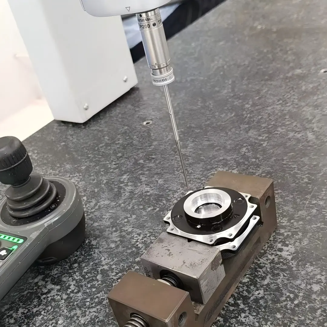
An RFQ for the supporting components should include the axis layout and the drive interfaces, not only isolated bracket models. Identify the linear-guide datums, rack locating faces, pinion axis, available adjustment directions and access for tightening and inspection.
Provide the intended operating travel, loading directions and environmental context to the responsible drive designer. The component supplier needs the released geometry and inspection requirements, while the drive specialist needs enough application information to confirm the selected mesh and preload arrangement. Keep those responsibilities distinct.
State which surfaces may be shimmed, which are final locating surfaces and which fasteners lock adjustment. Show any surfaces that must remain accessible after the carriage and guards are installed. A theoretically adjustable assembly can become impossible to commission when the access path is omitted.
For repeat builds, retain the measured alignment and final adjustment record alongside the drawing revision. If the frame or guide arrangement changes, review the mounting relationship rather than copying the previous pinion setting. The target is a reproducible installed drive, not a collection of individually conforming parts that require undocumented correction each time they are assembled.
FAQ
Can software backlash compensation replace a mechanical adjustment?
It can address a defined control-related reversal correction in an appropriate system, but it cannot restore damaged teeth, correct an uneven mounting surface or prevent a tight mesh from binding. Its effectiveness depends on where position is measured and whether the error is repeatable under the operating load. Establish the mechanical condition first, then validate any compensation across travel and duty. Preserve the mechanical and control settings together so maintenance does not unknowingly invalidate the correction.
Why does backlash seem different after the axis warms up?
Temperature can change the relative positions of the rack, frame, pinion support and bearings, while lubricant behavior and drive loading may also change. Compare the same measurement method at defined thermal states before attributing the change to gear wear. A cold setup should leave the selected drive within its permitted operating condition over the expected temperature range. If that relationship is unclear, review it with the drive designer instead of tightening the cold mesh further.
Does a clicking sound prove that a rack tooth is damaged?
No. A periodic sound can arise from a tooth defect, a segment joint, a loose support, contamination or another rotating component. Correlate the sound with carriage position and pinion rotation under a controlled inspection procedure. Inspect the affected area and stop operation where a mechanical fault is suspected. Do not use sound alone to assign a backlash value or to justify an adjustment that could conceal the original cause.
Conclusion
A reliable rack drive starts with the relationship between the rack, linear guides and pinion support. Set the intended mesh at the tightest relevant location, verify contact across travel and keep preload separate from basic alignment. Carriage lost motion remains a system measurement, so the rest of the drive chain must stay in the investigation.
Use a measurement map to distinguish a local joint problem from uniform clearance or load-dependent movement. The chosen response should match that evidence. A smaller backlash reading is useful only when the assembled drive remains correctly engaged and operates without binding through its required range.
For mounting components, send 6CProto the guide datums, rack interfaces, pinion bracket and adjustment requirements. This provides a clear basis for reviewing the machined load path and inspection access before the drive is assembled.
{“@context”: “https://schema.org”, “@type”: “FAQPage”, “mainEntity”: [{“@type”: “Question”, “name”: “Can software backlash compensation replace a mechanical adjustment?”, “acceptedAnswer”: {“@type”: “Answer”, “text”: “It can address a defined control-related reversal correction in an appropriate system, but it cannot restore damaged teeth, correct an uneven mounting surface or prevent a tight mesh from binding. Its effectiveness depends on where position is measured and whether the error is repeatable under the operating load. Establish the mechanical condition first, then validate any compensation across travel and duty. Preserve the mechanical and control settings together so maintenance does not unknowingly invalidate the correction.”}}, {“@type”: “Question”, “name”: “Why does backlash seem different after the axis warms up?”, “acceptedAnswer”: {“@type”: “Answer”, “text”: “Temperature can change the relative positions of the rack, frame, pinion support and bearings, while lubricant behavior and drive loading may also change. Compare the same measurement method at defined thermal states before attributing the change to gear wear. A cold setup should leave the selected drive within its permitted operating condition over the expected temperature range. If that relationship is unclear, review it with the drive designer instead of tightening the cold mesh further.”}}, {“@type”: “Question”, “name”: “Does a clicking sound prove that a rack tooth is damaged?”, “acceptedAnswer”: {“@type”: “Answer”, “text”: “No. A periodic sound can arise from a tooth defect, a segment joint, a loose support, contamination or another rotating component. Correlate the sound with carriage position and pinion rotation under a controlled inspection procedure. Inspect the affected area and stop operation where a mechanical fault is suspected. Do not use sound alone to assign a backlash value or to justify an adjustment that could conceal the original cause.”}}]}