

Hold a premium consumer device and the first impression is not the processor or the battery—it is the enclosure: the anodized A-side, the matte texture, the precise edge, the gap around the screen. An enclosure is a CMF (color, material, finish) product with fit requirements bolted on, and CNC machining carries both. The machining must keep 1.2 mm walls from deflecting under the cutter, deliver an anodizing color that holds across the batch, and hold the screen, lens, and button openings to the designed gaps—all in the same part. This guide covers the machining and finishing decisions that take an enclosure from drawing to production.
The Enclosure Is a CMF Product
The A-side surfaces carry the cosmetic requirement; the mating features carry the fit. A part that fits perfectly but shows color drift or a flawed surface fails the product, which is why finish and fit are specified together and the drawing separates them. The CMF decision starts with the material, because the material sets what the finish can deliver. Aluminum is the common enclosure metal for its weight, strength, and anodizing range. Within aluminum, the alloy choice directly affects the anodized result: 6063-family alloys anodize to a more uniform, brighter finish, while 6061 offers more strength. A product brief that says “matte black anodized aluminum” is only a starting point; the drawing must add the alloy, the surface prep, and the gloss target so the supplier can reproduce the intent.
Surface metrology is part of the CMF spec. Gloss units measure the shine, a texture standard or Ra value defines the grain, and a defined edge break sets the feel. The inspection of a cosmetic surface is only as useful as its reference—an approved sample that fixes the color, texture, and gloss under the product’s lighting. That sample is the contract between design and production line, and every batch is checked against it.
Thin Walls: Deflection, Vibration, and Support
Thin walls are the enclosure’s defining constraint. A wall that is too thin deflects under cutting force or vibrates during machining, leaving the surface wavy or the part distorted. The response is support and sequence: ribs where the design allows, uniform sections, and machining steps that keep the wall stiff. The wall is also a tolerance, not just a design value—a wall specified at 1.2 mm that varies between 1.0 and 1.4 mm changes the feel, the weight, and sometimes the fit of internal components. The drawing should call out the wall thickness where it matters—at mounting bosses, speaker or battery compartments, and the A-side—and inspection should verify it.
Thin-wall machining is also a tooling story. The tool that cuts a thin wall must be short and stiff enough to resist deflection itself, and the machining passes must remove material in a sequence that keeps the remaining wall supported. A common failure is machining both sides of a thin wall so the wall flutters between passes, leaving a wavy surface or a wall that varies in thickness. The finish pass on the A-side is typically run with light cuts and a fresh tool so the surface stays stable. None of this needs to be directed by the buyer, but the RFQ should flag the thin walls and the A-side so the supplier plans the tooling and the sequence. The DFM checklist for CNC machining exists precisely to surface these constraints before the quote becomes a commitment.
Wall Budget and Material Choice Come First
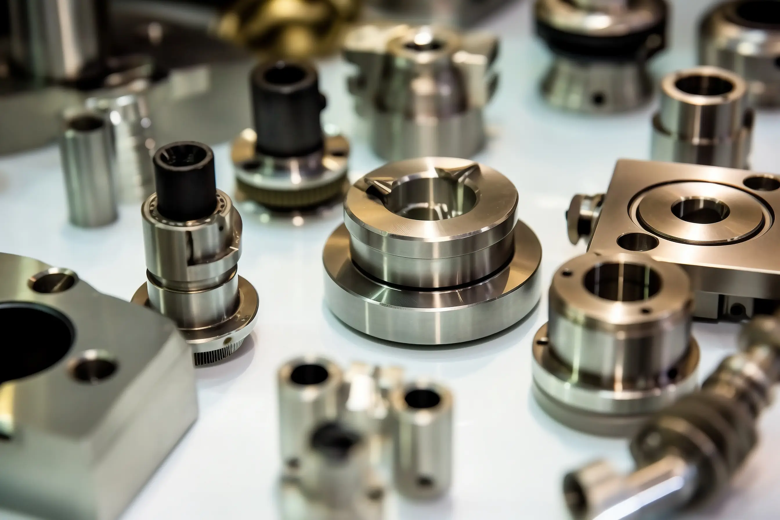
The wall budget is the enclosure’s structural blueprint: where the thin sections are, what they carry, and how they are supported. The practical approach is to design that budget before the internal features, because a speaker boss, a battery compartment, and an A-side all place different demands on the surrounding wall. A wall that must resist thumb pressure on a button well needs different design attention than a wall that only separates two internal components. The machining can implement the budget only if the drawing expresses it—thickness callouts at the mounting bosses, the speaker and battery compartments, and the A-side, plus the ribs that brace the long unsupported spans.
Material choice interacts with the wall budget. The common enclosure alloys are not interchangeable: 6061 offers better strength and machinability at a given thickness, while 6063-family alloys give a more uniform anodized finish but generally lower strength, which can force a thicker wall for the same deflection target. A thin-wall design driven to the strength limit may therefore need the 6061 route and a matte or dyed finish that tolerates its anodizing character, while a finish-driven design may accept a thicker 6063 wall to hit the brighter anodic surface. This is why the finish decision and the alloy decision must be made together, before the wall budget is locked.
Anodizing Color: Alloy, Batch, and Sample Control
Anodizing color is a batch story: the alloy, the tank, and the process conditions all shift the shade, and the color that matters is the one on the approved sample. Machining contributes the foundation, because anodizing reveals the finish—a machined surface with torn grain or inconsistent texture shows through the anodic layer. The color management workflow is simple on paper and demanding in practice: approve a sample, define an acceptable variance, and check every batch against it. The A-side gloss and texture are measured with instruments, and the batch is compared with the sample under standard lighting rather than by memory. When the sample ages or the process drifts, the sample is re-approved rather than guessed at. For enclosure programs, requesting the surface finishing step together with machining keeps the anodic layer, the gloss, and the texture under the same quality system—this is the surface finishing scope a premium enclosure actually needs.
Screen, Lens, and Button Fits
The screen pocket, lens opening, and button wells are the customer-facing fits, and they carry tight tolerances because the user sees and presses them. A screen pocket that is too loose allows movement and dust ingress; one that is too tight makes assembly impossible or cracks the glass under the first thermal cycle. The lens opening must hold a controlled gap around the perimeter so the adhesive or gasket seals consistently. Button wells add a mechanical dimension: travel, tactile feel, and seal. The well must be machined for the button’s required travel and the gasket’s compression, with edges clean enough not to catch the button. For enclosures with many buttons, the wells are often the most inspection-heavy features because each one is a user-facing interaction. The drawing should state the required travel and force so the assembly check verifies behavior rather than merely position.
Datums, Tolerance Flow, and the Fit Chain
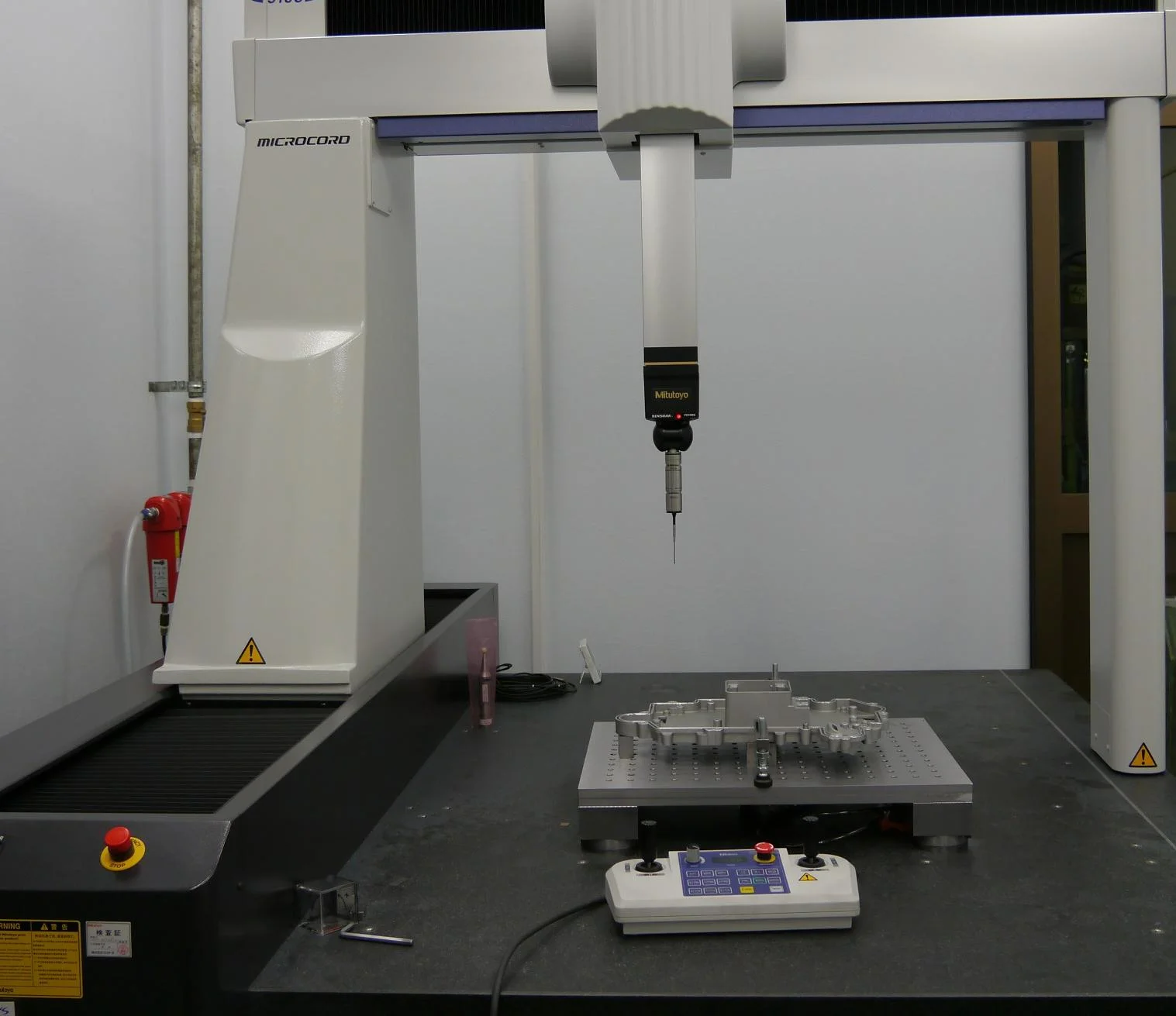
An enclosure’s fits are only as good as its datum system. If the screen pocket, the lens opening, and the button wells are dimensioned from different datums, the machining tolerance stacks across the part and the assembly gaps become unpredictable. The drawing should establish one master datum—usually a flat mounting face or a pair of locating bosses—and reference the customer-facing fits from it, so the tolerance does not accumulate through intermediate features. The practical guide to CNC machining tolerances explains what those numbers realistically buy: sub-hundredth control on critical fits, with looser figures available elsewhere in the part.
Tolerance flow also decides where inspection effort goes, and the measurement traceability behind it ultimately rests on national measurement references. The critical fits carry the tight tolerances and are measured on every part or on a statistically sound sample, while cosmetic and structural features use looser, functional numbers. If the drawing applies one general tolerance to every feature, the supplier must either inspect everything to the tightest number—raising cost—or risk missing a drift where the tight number actually mattered. Separating the fit tolerances from the general tolerance is the difference between an inspectable drawing and an expensive argument.
Cosmetic Surface Inspection Standards
Cosmetic surfaces need inspection standards: the color, the texture, the edge condition, and the defects that are acceptable. A visible tool mark, a scratched A-side, or a color mismatch fails the standard, so the criteria must be defined with the sample and the lighting before the batch runs. A gloss meter checks the A-side shine against the sample, a texture or surface standard checks the grain, and a light booth with standard lamps checks the color. Edge condition is checked by touch and by gauge, because a sharp or ragged edge is both a defect and a safety issue. The inspection should be documented with the part—the batch record ties each unit to the criteria it met. For high-volume enclosures the cosmetic inspection may be a sampling plan; for low-volume and premium products it is often 100% on the visible surfaces. Sample retention closes the loop: the approved sample is kept, dated, and used as the reference for every batch.
From Prototype Enclosure to Production
The prototype validates the finish and the fit; the production run repeats them. The transition works when the functional geometry and the finish standard stay constant across the process change, and it fails when inspection scope shrinks silently. The prototype is inspected individually, with the engineer’s eye; the production run needs defined criteria, sampling, and records that scale. The buyer should use the prototype approval to write those criteria—acceptable defects, measurement points, and report format—so production inspection tests the same things the prototype proved. The cost structure changes with volume too: machined enclosures carry programming, setup, and machine-time costs that fall with quantity, while finish and inspection add per-part steps. A tooled process such as casting or molding becomes attractive when volume justifies the tooling and the functional geometry can be reproduced. The buyer should compare the machined and tooled routes at the forecast quantity before committing to either. The CNC machining service and the plastic injection molding route each have different crossover points, and the forecast—not the prototype—decides which one wins.
FAQs
Why does anodizing color vary between batches?
Because the alloy, tank, and process conditions shift the shade. The enclosure program manages it with an approved sample, a defined variance, and batch checks against the sample.
How are thin enclosure walls machined without distortion?
With support and sequence: ribs where the design allows, uniform sections, and machining steps that keep the wall stiff. The deflection is designed out before the cut.
What are the critical fits in an enclosure?
The screen pocket, lens opening, and button wells. They carry tight tolerances and controlled gaps because the customer sees and presses them.
What should an enclosure RFQ include?
The finish references and sample, the A-side callouts, the fit tolerances, and the cosmetic inspection criteria. These let the engineering team review the finish and fit before production.