

An RF enclosure that measures perfectly as a bare aluminum box fails its shielding test once the cover is screwed on and a gasket is fitted — the seam leaks at the corners, the gasket seat is too rough, or the plating thickness varies where the cover meets the wall. RF performance is decided at the seams, the gasket seats, and the surface conductivity, not on the flat faces that look finished. CNC machined RF enclosures are precision shielding structures: the material, the plating, the gasket geometry, and the fastener pattern work together, and each is a machining and finishing requirement that the drawing must carry.
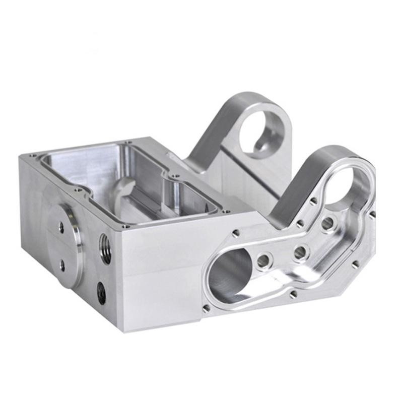
RF performance starts with material and plating choices
The enclosure’s shielding starts with the material’s conductivity and the surface that carries the RF current. Aluminum and copper alloys conduct well and are machinable; steel adds strength and magnetic shielding but lower conductivity at the surface; and the finish changes the picture — bare aluminum oxidizes and can raise contact resistance, so critical seams are often plated, chromate-treated, or masked during anodizing. The plating choice balances conductivity, corrosion, and cost: silver and tin plate well but differ in cost and environment behavior, while conductive gaskets can bridge a seam that plating alone cannot make reliable. The RF requirement should name the shielding target and the surface conductivity expectation, because the material and finish follow the specification, not the catalog.
Machining features that make or break RF sealing
RF leakage concentrates at seams, so the machining features at the seam decide the result. The gasket seat must be flat and smooth enough for the gasket to compress evenly; the cover-mating surface must be square so the fastener pattern loads the gasket uniformly; and the corners where walls meet must carry the gasket without a gap. Machined enclosures earn their place in RF work precisely because these features can be held precisely — the flatness, the surface finish, and the corner geometry are machined, not formed. The drawing should mark the sealing surfaces, their flatness and finish, and the fastener spacing that loads them.
Compartment walls inside the enclosure create separate shielded zones, and the wall-to-cover seam is another leakage path. If the design separates RF sections, each compartment wall needs its own gasket seat or an interference detail with the cover, and the machining must hold the wall height and the cover fit so the seam closes at every point.
Gasket seats, cover screws, and compartment walls
Gasket selection and the seat geometry are a pair. A conductive elastomer gasket needs a defined groove or a flat seat with the right compression; a finger-stock gasket needs a clean mounting surface and enough height to engage the cover; a knife-edge or interference seal needs controlled geometry on both parts. The seat width, depth, and finish should be specified from the gasket data, and the cover screw spacing should be close enough to hold the gasket at the specified compression across the whole perimeter. The fastener pattern is part of the RF design, not a mechanical afterthought.
The gasket also carries a maintenance requirement: a gasket that is crushed, contaminated, or replaced with an untested type changes the shielding. The drawing and the assembly note should name the gasket part and the compression, so the field replacement does not silently degrade the enclosure.
When to machine vs shield via coating
Not every RF enclosure needs a fully machined, gasketed construction. A plastic enclosure with a conductive coating or a sprayed shield can serve lower-frequency or lower-sensitivity applications at lower cost, and a stamped metal shell with formed fingers can work where the tolerance budget allows. The machined enclosure earns its cost when the shielding requirement is high, the geometry is complex, or the seams must be precise and repeatable. The decision is a specification trade: name the shielding target, the frequency range, and the environmental condition, and choose the construction that meets them at the lowest total cost. The machined route wins where precision and repeatability dominate; the coated or formed route wins where cost and weight dominate.
Hybrid constructions are common: a machined chassis with a coated or stamped cover, or a machined gasket seat on a formed enclosure. The drawing should state which parts carry the RF responsibility, because the shield is only as strong as the weakest seam in the assembly.
Drawing and inspection notes for RF housings
An RF enclosure drawing should name the shielding surfaces, the gasket seats with their flatness and finish, the fastener pattern and spacing, the plating or surface treatment with its conductivity requirement, and the assembly notes for the gasket. The inspection plan should verify the sealing surfaces with the same method the RF test will use — a flatness check on the seat, a finish check on the gasket area, and a dimensional check on the fastener pattern. If the enclosure is validated by a shielding test, the test should be run on the finished assembly with the production gasket, because the bare enclosure result does not predict the assembled result.
The enclosure capability on this site covers the manufacturing route; the RF notes above are what turn a machined box into a shielding structure. When the RF requirement is on the drawing, the shop can machine and finish the seams that make the difference, and the first shielding test becomes a confirmation rather than a surprise.
Why the seam decides the shielding result
A shielding example shows how the machining decisions connect to the test. A telecom housing must meet a shielding requirement across its operating band, and the first machined prototype fails at the cover seam. The review looks at the seam: the gasket seat is within its flatness callout, but the cover screws are spaced too far apart, so the gasket is not compressed evenly near the middle of the long edges, and the corners leak. The fix is not a thicker gasket; it is a fastener pattern that loads the gasket uniformly, with the screw spacing chosen from the gasket’s compression data. The drawing is revised with the new spacing, the gasket seat finish is confirmed, and the second prototype passes the shielding test. The example shows why RF performance is a mechanical design: the gasket, the fastener pattern, the seat flatness, and the surface conductivity are all machined and assembled features, and the shielding test is the verification of the whole system, not of the enclosure alone.
The same logic extends to the corners and the compartment walls. A shielded enclosure with an internal wall that divides sections depends on the wall-to-cover seam as much as on the outer seam, and the wall height and the cover detail must be machined so the seam closes at every point. The drawing should show the gasket path across the corners, where the seal turns and the risk of a gap is highest, and the inspection should verify the seat along the full path, not just on the straight edges. When the enclosure is validated, the test should be run on the finished assembly with the production gasket and fasteners, because the bare enclosure result does not predict the assembled performance. The supplier that machines the seat, plates the surface, and assembles the gasket to the drawing is the supplier that produces a housing that passes the first test.
Signs that a seam design will leak in testing: the fastener spacing was copied from a structural drawing rather than from the gasket data, the gasket seat finish is unspecified, the corners have no gasket path note, or the plating thickness is not controlled on the mating faces. Each sign is a design decision that can be corrected before machining. The review should trace the gasket path around the full perimeter and ask where the compression will be lowest, where the surface conductivity will be worst, and where a gap can open. The drawing should carry the answers: the gasket part and compression, the fastener spacing, the seat finish, and the surface treatment. When those notes are on the drawing, the machined enclosure and the assembled test have a shared expectation, and the first shielding test is a verification of the design rather than a discovery of its gaps.
Keep the RF requirement visible on the drawing rather than in a separate email: the shielding target, the frequency range, and the test method belong with the part notes, because they explain why the seams and the plating are specified as they are. The supplier that sees the requirement can flag a conflict between the geometry and the target before machining, and the buyer can adjust the design while it is still a drawing. That early flag is the real value of a complete RF specification — it moves the risk conversation from the test lab to the design review.
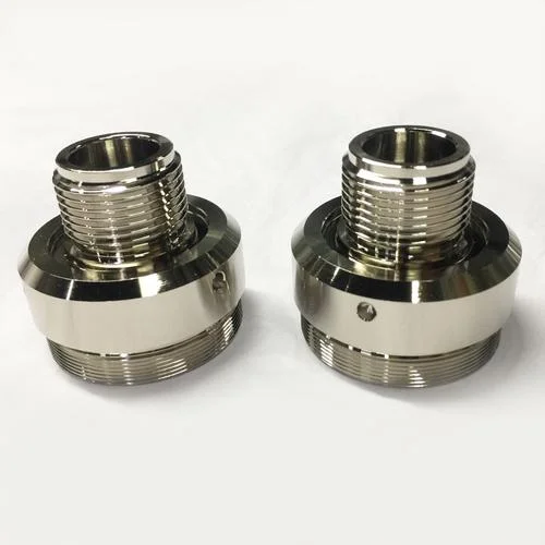
If you are developing a machined RF enclosure and want the material, plating, and gasket-seat design reviewed before machining, the 6CProto CNC and surface finishing teams can work from the shielding target to the drawing and the test plan.