
Sheet Metal Fabrication Design Tips
Sheet Metal Hole-to-Bend Distance: How to Prevent Hole Deformation During Bending
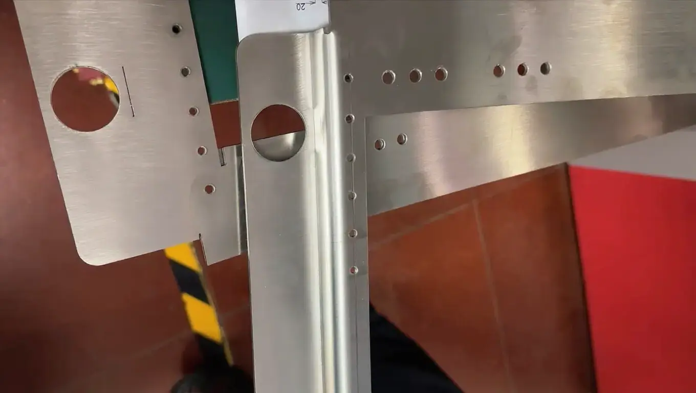
A hole can be perfectly round in the flat sheet and still become distorted after bending.
This is a common sheet metal design problem.
The laser-cut or punched hole may be completely within tolerance before forming, but after the part comes off the press brake, the hole may become:
- oval,
- stretched,
- teardrop-shaped,
- shifted from its intended location,
- or locally cracked.
In many cases, the hole itself is not the problem.
The real problem is that the hole is too close to the bend line and enters the sheet metal deformation zone during bending.
For designers, this means hole location should not be determined only by assembly requirements.
The bend radius, material thickness, hole geometry, and actual forming process also need to be considered.
What Is the Minimum Hole-to-Bend Distance in Sheet Metal?
As a practical sheet metal DFM starting point, the minimum distance S should be measured from the nearest edge of the hole to the bend line.
For a round hole in thin sheet, a useful starting relationship is:
S ≥ T + R
Where:
- S = minimum distance from the hole edge to the bend line
- T = sheet metal thickness
- R = inside bend radius
For thicker materials and more deformation-sensitive features such as square holes and obround slots, a larger clearance should normally be considered.
A practical starting guide is:
| Feature Type | Material / Feature Condition | Practical DFM Starting Point |
|---|---|---|
| Round hole | T ≤ 2 mm | S ≥ T + R |
| Round hole | 2 < T ≤ 6 mm | S ≥ 1.5T + R |
| Round hole | 6 < T ≤ 25 mm | S ≥ 2T + R |
| Square or obround hole | Feature length ≤ 25 mm | S ≥ 2T + R |
These values should be treated as practical DFM guidelines rather than universal standards.
The final required distance can change depending on:
- material,
- sheet thickness,
- bend radius,
- bending method,
- tooling,
- feature size,
- bend direction,
- and final dimensional tolerance.
For critical components, the design should be reviewed with the sheet metal manufacturer before production.
Why Do Holes Deform Near a Sheet Metal Bend?
Sheet metal does not simply rotate around a mathematical bend line.
During bending, a physical deformation zone forms around the bend.
Material on the outside of the bend is stretched, while material on the inside of the bend is compressed.
The strongest deformation occurs around the bend radius.
As the distance from the bend increases, the influence of the forming process gradually decreases.
If the edge of a hole falls inside this highly strained region, the surrounding sheet metal moves during bending and pulls on the hole.
The result is feature distortion.
A round hole may become oval.
A hole close to one side of the bend may develop a teardrop-like shape.
The hole center may also shift relative to its original position.
If the remaining material between the hole and the bend is too narrow, cracking or tearing can occur.
The basic design principle is therefore:
Keep critical holes and cutouts outside the severe bend deformation zone whenever possible.
Measure Hole-to-Bend Distance From the Hole Edge, Not the Hole Center
This is an important detail that is often misunderstood.
The distance S refers to the shortest distance from the nearest hole edge to the bend line.
It is not measured from the hole center.
For example, consider a 10 mm diameter hole.
If the center of the hole is 8 mm from the bend line:
- Hole radius = 5 mm
- Center-to-bend distance = 8 mm
The actual hole-edge distance is:
S = 8 − 5 = 3 mm
The 3 mm value is what should be evaluated against the hole-to-bend guideline.
This becomes especially important for large holes.
Two holes can have exactly the same center-to-bend dimension but very different edge clearances if their diameters are different.
Round Hole-to-Bend Distance Guidelines
Round holes are generally less sensitive to local stress concentration than square or rectangular openings.
However, they can still deform significantly if they are placed inside the bend deformation zone.
Round Holes in Thin Sheet: T ≤ 2 mm
For common thin sheet applications, a practical starting point is:
S ≥ T + R
For example:
- Sheet thickness T = 1.5 mm
- Inside bend radius R = 1.0 mm
Then:
S ≥ 1.5 + 1.0
S ≥ 2.5 mm
The nearest edge of the hole should therefore be approximately 2.5 mm or more from the bend line as an initial DFM reference.
This value should still be checked against the actual material and forming process.
Round Holes in Medium-Thickness Sheet: 2 < T ≤ 6 mm
As material thickness increases, a more conservative starting relationship is:
S ≥ 1.5T + R
For example:
- T = 3 mm
- R = 2 mm
Then:
S ≥ (1.5 × 3) + 2
S ≥ 6.5 mm
The larger spacing helps keep the feature farther away from the increasingly large deformation zone.
Round Holes in Thick Sheet: 6 < T ≤ 25 mm
For thicker plate, forming forces increase and the bend zone generally becomes more significant.
A practical starting relationship is:
S ≥ 2T + R
For example:
- T = 8 mm
- R = 8 mm
Then:
S ≥ (2 × 8) + 8
S ≥ 24 mm
Thick plate forming should always be reviewed with the actual tooling and bending process in mind.
Square and Obround Holes Need More Clearance
A square hole does not behave exactly like a round hole during bending.
Square and rectangular holes introduce corners.
These corners can act as local stress concentration points when the surrounding material is stretched.
Obround or waist-shaped slots can also have relatively long edges extending toward or parallel to the bend.
Because of this, these feature types are often more sensitive to distortion.
For square and obround holes with an overall feature length of approximately 25 mm or less, a practical DFM starting point is:
S ≥ 2T + R
This larger safety margin helps reduce the risk of:
- corner stretching,
- slot deformation,
- local cracking,
- dimensional shift,
- and distortion at the bend edge.
For longer slots, large rectangular cutouts, or complex openings, a single formula may no longer be sufficient.
The entire geometry should be reviewed.
Why Are Square Holes More Sensitive to Bending?
A circular hole distributes deformation around a continuous curved boundary.
A square hole contains abrupt geometric changes at each corner.
When the sheet is stretched during bending, these corners tend to concentrate local strain.
The same problem may occur with:
- rectangular cutouts,
- connector openings,
- ventilation slots,
- large windows,
- and complex laser-cut profiles.
Therefore, hole-to-bend distance should not be evaluated only according to feature size.
Feature geometry also matters.
What Happens When a Hole Is Too Close to a Bend?
Several different types of failure may occur.
1. A Round Hole Becomes Oval
The material surrounding the hole is stretched during bending.
The hole loses circularity and becomes elongated.
This can cause assembly problems for:
- bolts,
- locating pins,
- bushings,
- inserts,
- and other mating components.
2. The Hole Becomes Teardrop-Shaped
If one side of the hole is much closer to the bend than the other, the material near the bend may be pulled more aggressively.
The side closest to the bend deforms while the opposite side remains relatively stable.
This can produce a characteristic teardrop-shaped opening.
3. The Hole Position Changes
The hole may remain usable but move relative to its intended location.
This can create problems when several holes must align with:
- another sheet metal component,
- a PCB,
- a connector,
- a bracket,
- a threaded insert,
- or an assembly fixture.
4. The Material Cracks or Tears
When too little material remains between the bend and the feature, strain can become concentrated in the narrow section.
This may cause:
- cracking,
- tearing,
- edge splitting,
- or unstable deformation.
Sharp corners make this risk more significant.
5. The Flat Pattern Passes Inspection but the Formed Part Fails
This is one of the most frustrating situations in sheet metal manufacturing.
The flat blank may be completely correct.
The laser cutter or punch produces the feature within tolerance.
Inspection before bending finds no problem.
But after press-brake forming, the hole is out of tolerance.
This demonstrates an important sheet metal DFM principle:
The final formed geometry matters more than the flat pattern alone.
What Can You Do If the Hole Cannot Be Moved?
Moving the hole farther from the bend is normally the simplest solution.
But this is not always possible.
The feature location may be fixed by:
- a mating component,
- an assembly interface,
- connector position,
- PCB location,
- fastener position,
- limited enclosure space,
- or another functional requirement.
When the hole cannot be moved, several process solutions can be considered.
Solution 1: Add a Relief Slot Between the Hole and Bend
One approach is to add a small process relief between the critical feature and the bend region.
The purpose of the relief is to interrupt the path through which bending strain is transferred into the hole.
Instead of allowing the surrounding sheet to pull directly on the hole edge, the relief creates a controlled separation.
This can help reduce distortion.
However, the relief must be evaluated carefully.
It should not negatively affect:
- structural strength,
- sealing,
- appearance,
- fatigue resistance,
- electrical shielding,
- or assembly performance.
Solution 2: Extend the Cutout Toward the Bend Region
For some components, the feature itself can be extended toward the bend.
Instead of leaving a narrow strip of material between the feature and the bend that is likely to deform unpredictably, that material is intentionally removed.
The cutout then becomes part of the bend-relief geometry.
This approach can be useful for:
- elongated slots,
- rectangular openings,
- connector openings,
- and other non-critical cutout shapes.
The final opening must still meet the functional requirements of the component.
Solution 3: Bend First, Then Machine the Hole
When the hole position and final shape are critical, another effective solution is to change the manufacturing sequence.
Instead of:
cut hole → bend part
the process becomes:
bend part → machine hole
Possible secondary operations include:
- drilling,
- CNC milling,
- secondary punching when tooling access allows,
- or laser cutting when the formed geometry can still be accessed.
Because the hole is produced after the major forming deformation has already occurred, final geometry can be controlled more accurately.
The disadvantage is that an additional setup is required.
This usually increases:
- manufacturing time,
- handling,
- fixturing,
- and cost.
However, for precision sheet metal parts, the additional operation may be more economical than dealing with repeated deformation and rejected parts.
Solution 4: Review the Bend Radius and Tooling
The inside bend radius directly affects the size and severity of the deformation zone.
A larger radius generally involves a larger region of material in the bend.
The tooling and forming method also influence how the sheet moves.
Therefore, when a critical hole is close to a bend, review:
- inside bend radius,
- punch radius,
- die opening,
- air bending versus bottoming,
- material condition,
- and bend direction.
The CAD geometry should reflect the actual forming process wherever possible.
Practical Example: A Hole Near a Bend
Consider a 1.5 mm stainless steel bracket with:
- Sheet thickness: T = 1.5 mm
- Inside bend radius: R = 1.0 mm
For a round hole in thin sheet:
S ≥ T + R
Therefore:
S ≥ 2.5 mm
Now consider a short obround or square opening.
Using the more conservative practical guideline:
S ≥ 2T + R
Therefore:
S ≥ 4.0 mm
If the CAD model places the hole edge only 1 mm from the bend line, the feature is likely to experience significant deformation.
The designer should consider:
- moving the feature,
- adding a relief,
- extending the cutout,
- changing the bend geometry,
- or producing the feature after bending.
Solving the problem during design is normally much easier than trying to correct distorted parts after production.
Does Every Sheet Metal Part Use the Same Hole-to-Bend Formula?
No.
There is no single hole-to-bend formula that should automatically be applied to every sheet metal component.
The required distance depends on several interacting variables:
| Factor | Why It Matters |
|---|---|
| Material | Different alloys have different ductility and forming behavior |
| Thickness | Thicker material creates a larger and more heavily loaded bend zone |
| Inside radius | Bend radius influences the geometry of the deformation region |
| Hole shape | Round, square, and elongated features respond differently |
| Tooling | Punch and die geometry affect material flow |
| Bend method | Air bending and other forming methods do not produce identical strain distributions |
| Tolerance | Precision locating holes require more conservative control |
| Hole size | Larger holes can extend much closer to the bend even if their centers appear far away |
For this reason, formulas such as:
T + R
1.5T + R
and
2T + R
should be used as practical design-review starting points.
They do not replace a manufacturing review for a critical component.
Hole-to-Bend Distance Is a DFM Issue, Not Just a CAD Dimension
CAD software allows a designer to position a hole almost anywhere.
The model may look completely correct on the screen.
But the press brake has to physically stretch and compress the material.
That means a good sheet metal design should consider:
- how the material flows,
- where the deformation zone develops,
- how the bend radius forms,
- where the punch and die contact the sheet,
- and whether critical features are located inside that region.
Good DFM connects CAD geometry with real manufacturing behavior.
Sheet Metal Hole-to-Bend Design Checklist
Before releasing a sheet metal drawing, check the following:
- Measure the distance from the hole edge, not the hole center.
- Confirm the actual material thickness.
- Confirm the intended inside bend radius.
- Identify whether the feature is round, square, rectangular, or obround.
- Give square holes and elongated slots more clearance where possible.
- Review locating holes and assembly holes separately from non-critical openings.
- Avoid placing sharp corners directly inside the bend deformation zone.
- Consider a relief if the feature cannot be moved.
- Consider machining the hole after bending when final position is critical.
- Review unusual geometry with the manufacturer before production.
These checks can prevent distortion before the first part reaches the press brake.
Engineering Note From 6CProto
The relationships in this guide are intended as practical DFM starting points for sheet metal design.
They should not be interpreted as universal forming standards.
Actual performance depends on:
- material,
- thickness,
- bend radius,
- tooling,
- forming method,
- feature geometry,
- tolerance,
- and production conditions.
For critical holes, slots, connector openings, or precision assemblies, the geometry should be reviewed before the drawing is released for manufacturing.
Frequently Asked Questions
What is the minimum distance between a hole and a sheet metal bend?
For a round hole in thin sheet, S ≥ T + R is a useful practical starting point, where S is the hole-edge-to-bend-line distance, T is sheet thickness, and R is the inside bend radius.
Thicker material or more deformation-sensitive feature shapes may require greater clearance.
Is hole-to-bend distance measured from the hole center?
No.
The distance should normally be evaluated from the nearest edge of the hole to the bend line.
This is especially important for larger holes.
Why does a round hole become oval after bending?
The sheet metal surrounding the hole is stretched and compressed during forming.
If the hole falls inside the bend deformation zone, the moving material pulls on the hole edge and changes its geometry.
Why can a hole become teardrop-shaped after bending?
When one side of a hole is much closer to the bend, the side nearest the bend experiences greater deformation.
This asymmetric strain can stretch one side of the hole and produce a teardrop-like shape.
Do square holes need more distance from a bend?
In many cases, yes.
Square holes introduce corners where strain can become concentrated.
For small square and obround features, S ≥ 2T + R can be used as a practical initial DFM guideline.
Can a hole be placed directly next to a sheet metal bend?
It may be physically possible, but significant feature distortion should be expected unless the part is specifically designed to accommodate that deformation.
For critical holes, greater clearance is normally preferred.
What should I do if the hole cannot be moved?
Possible solutions include:
- adding a bend relief,
- extending the cutout toward the bend,
- changing the bend geometry,
- or producing the hole after bending.
The best option depends on the functional requirements and production quantity.
Can I make the hole after bending?
Yes.
When final hole position or circularity is critical, bending the component first and machining the feature afterward can be an effective solution.
The trade-off is an additional manufacturing operation.
Does this apply to both laser-cut and punched holes?
Yes.
Once the feature exists in the flat sheet, the bending mechanism affects it regardless of whether the hole was created by laser cutting or punching.
If the hole is too close to the deformation zone, it can still distort during forming.
Design for the Formed Part, Not Only the Flat Pattern
A perfect hole in the flat pattern does not guarantee a perfect hole after bending.
The important question is:
Will the feature still meet its dimensional and functional requirements after the material has been formed?
If sufficient clearance is not available, use a controlled engineering solution such as:
feature relocation → bend relief → modified cutout → post-bend machining
instead of allowing an uncontrolled bend to distort a critical feature.
Need a Sheet Metal DFM Review?
If your sheet metal design includes:
- holes close to bends,
- complex slots,
- connector openings,
- tight dimensional tolerances,
- multiple bends,
- precision assembly features,
- or difficult-to-form geometry,
6CProto can review the CAD model and drawing before production.
Our DFM review can consider:
- material selection,
- sheet thickness,
- bend radius,
- hole-to-bend distance,
- bend relief,
- manufacturability,
- tolerance,
- and suitable production sequence.
Upload your 3D CAD model and drawing for a sheet metal DFM review.