

A taper callout can be mathematically clear and still leave the wire EDM setup ambiguous. The programmer needs to know which profile belongs to which plane, how those planes relate to the workpiece and whether the required wall is a simple taper or a transition between different contours. Wire EDM taper cutting starts with that geometric definition.
The important acceptance question is the finished surface between the planes. Matching the top and bottom openings does not prove that the middle of the wall is straight or that a corner transition meets its profile. Wire behavior, flushing, material thickness and the selected cutting sequence can influence that result.
This guide addresses feature definition and verification rather than machine-specific setup commands. The machine, guide configuration, wire and control determine the available taper envelope. A quoted maximum angle should not be applied to every workpiece height, corner or surface requirement.
For an EDM component review, provide the two plane profiles and functional surface requirements together. A single draft angle on an otherwise incomplete model is a weak basis for comparing quotations, especially when the wall must fit another tapered component or maintain a controlled contact pattern.
Which planes define wire EDM taper cutting?
Define both profiles and their physical reference planes.
For wire EDM taper cutting, identify the upper and lower contours, their heights and their alignment to the part datums before choosing angle compensation or programming assumptions.
A simple tapered wall can be defined by one profile and a signed angle when the reference plane and direction are unambiguous. More complex four-axis work may require different upper and lower profiles with explicit correspondence. Reversing the workpiece orientation can otherwise reverse an intended widening direction.
Makino's wire EDM tutorial explains the independent upper-guide motion used to incline the wire. The workpiece profile planes are geometric inputs; the physical wire-guide planes are machine setup inputs. They should not be silently treated as the same locations.
Show the part datum, the two profile-plane heights and the direction of taper on a section. Identify whether an angle is measured from the vertical wall direction or another reference. If the upper and lower contours differ in topology or segment count, review how their features correspond. An apparently correct pair of outlines can create an unintended twisted or ruled transition when the linking convention is left undefined.
Relate workpiece height to the machine taper envelope
Workpiece height affects the lateral difference between profile planes and the machine setup needed to realize it. The actual usable height includes the relevant geometry and clearance, while guide separation and offsets depend on the selected machine and fixturing arrangement.
Do not interpret a maximum taper angle as an unrestricted part capability. Mitsubishi Electric's wire EDM catalog identifies a dedicated guide arrangement for a particular high-angle option. That association demonstrates why guide configuration matters; its advertised angle is not a general limit or promise for another machine.
Provide the measured or controlled height between the specified planes. If the stock faces are not parallel or a relief changes the section, show that geometry rather than supplying one nominal thickness. The programmer must understand which surfaces define the taper and which merely provide stock or access.
Check the fixture and nozzle envelope at the required inclination. A wire path that clears the finished wall can still conflict with surrounding stock or support features. For a component with prior turned locating surfaces, retain a clear relationship between those datums and the EDM setup so that the taper is not correct about the wrong axis.
Review corners, wire behavior and flushing access
Corners deserve separate review because the wire is a flexible electrode. A change in cutting direction, local thickness or flushing can affect the wall near a transition. A satisfactory long straight wall does not establish the same result around every small radius.
Identify which corners are functional and which can accept relief. Show the upper and lower radii separately when they differ, and confirm that the intended connecting surface is feasible with the selected wire and path. Avoid assigning a zero internal radius simply because the top-view CAD uses a sharp vertex.
Sodick's manufacturer training manual, hosted by MIT treats taper programming, guide geometry and machine-specific limits as linked subjects. Its examples apply to the described control and configuration; they should not be converted into universal setup numbers.
Flushing access should be reviewed where nozzles cannot remain close to the work or where the section is interrupted. Discuss the proposed cutting and finishing strategy with the specialist, then verify the sensitive corner on a representative feature. A generic instruction to add skim passes does not prove that the original error will be removed, particularly if the initial cut leaves a significant through-height deviation.
Inspect the functional wall between the profile planes
Inspection should follow the functional contact. For a locating wedge, the wall angle and position may control seating. For a tapered aperture, the two profile sizes and the surface connecting them may all matter. Define those characteristics before choosing the measurement method.
Measure more than two edge outlines where the wall itself is controlled. An intermediate section or suitable surface measurement can reveal bow, mismatch or a localized corner error. The instrument must be able to reach the required region without assuming a surface from a few convenient edge points.
Where contact with a mating component is important, an agreed functional check can supplement dimensional measurement. It should not replace the geometric report unless that acceptance basis is intentional. A part can seat at one edge and leave an unintended gap elsewhere.
Use the applicable dimensioning and tolerancing framework to communicate profile, orientation and datum relationships, with the actual limits selected for the application. The inspection scope should distinguish angle, upper and lower contour, intermediate wall form and surface condition. A report containing only angle can leave the most important fit requirement unanswered.
Preserve access and datums through the taper-cut sequence
The manufacturing sequence must preserve access and the datum relationship. Establish the stock and locating surfaces, prepare the wire entry where needed, rough cut the feature, complete the agreed finishing sequence and inspect the final released condition. Each stage should have a defined purpose rather than follow an assumed universal number of passes.
Draw the entry and exit path relative to the functional wall. A witness at the start location may be unacceptable on a contact surface but tolerable in a nonfunctional relief. Locate it intentionally. Also identify the retained part and the released slug so their movement does not damage the finished profile.
Makino's taper-machining session description separates standard taper and four-axis taper setup, supporting the need to define the programming scope. It does not supply a transferable machine recipe or a certified result for an unrelated component.
For a first build, plan how the feature will be held and measured after separation. If the component is thin or flexible, the clamped contour can differ from the free state. Acceptance should represent the intended support condition, with any fixture simulation explained in the inspection procedure rather than assumed from the cutting setup.
Compare contour, wall-form and surface evidence
The verification matrix should connect each functional requirement to a reachable measurement. Different checks can use different equipment, but their datums and part state must agree. This prevents a collection of locally favorable measurements from describing incompatible setups.
| Characteristic | Definition needed | Possible evidence | Boundary |
|---|---|---|---|
| Upper profile | Plane height and datum relationship | Contour measurement at that plane | Does not establish the lower profile |
| Lower profile | Plane height and taper direction | Accessible contour measurement | Does not establish mid-wall form |
| Functional wall | Profile or angle and form requirement | Suitable surface or sectional measurements | Sampling must represent critical regions |
| Surface condition | Final texture or integrity requirement | Specified examination or test | Not inferred from geometry alone |
For a simple example, assume profile planes 20 mm apart and a wall angle of 3 degrees from vertical. The lateral change for one wall is 20 tan(3 degrees) = 1.048 mm. A symmetric opening widening on both sides changes total width by about 2.096 mm. These assumed values establish nominal geometry only; they do not define a tolerance, machine setting or acceptable surface form.
Choose a trial that represents the difficult taper region
A trial should reproduce the difficult part of the feature. A straight taper coupon may establish a basic setup while failing to represent a small corner, interrupted thickness or restricted flushing condition on the production part. Choose the trial geometry from the actual uncertainty.
Record material, thickness, wire, machine configuration, profile definitions and finishing sequence. Compare the measured upper, lower and intermediate regions against the same datum scheme used for the final drawing. If the process changes, identify which evidence must be repeated.
Surface integrity is a separate requirement where the application makes it consequential. Makino's advanced EDM aerospace process material illustrates the specialist nature of process development for demanding applications. It does not establish that an ordinary taper-cut component meets aerospace requirements, nor that an attractive surface proves an acceptable subsurface condition.
Keep trial conclusions narrow. A passing sample can support the demonstrated combination of geometry and process; it does not certify every angle or height on the machine. Where the production feature differs, explain the relationship or obtain additional evidence. This is especially important when a quote depends on an advertised maximum capability rather than a review of the actual corner and surface requirements.
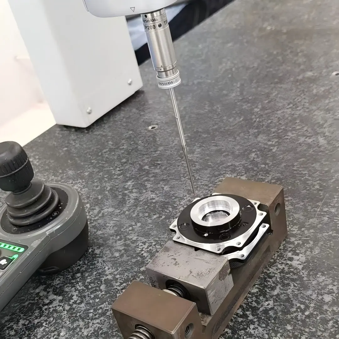
Supply complete taper geometry in the EDM RFQ
A specialist RFQ should identify the electrically conductive material, final condition, workpiece height and the two profile planes. Include the controlled model and drawing, taper direction, datum surfaces and any prior-machined features used for location.
Show wire access, proposed start regions, restricted surfaces and the handling of the released slug. Identify small corners, interrupted sections and surfaces that will contact a mating component. If the taper is part of a fit, include the mating definition or the acceptance gauge requirements.
State the required final texture and any surface-integrity examination separately from dimensional limits. Do not assume that an unspecified extra finishing pass resolves both. Request the proposed inspection approach and any exceptions before the order is released.
For repeat orders, preserve the profile-plane definition and approved process assumptions with the revision record. A change in thickness or reference height can alter the required transition even when the top profile remains identical. The review should therefore follow the complete surface, not just the easiest outline to compare on a drawing or in a quotation attachment.
FAQ
Can wire EDM make a blind tapered cavity?
Conventional wire cutting requires a continuous wire path through the workpiece, so a blind cavity is not equivalent to a through tapered opening. Another process or a changed component arrangement may be needed. Review the complete geometry before assigning the feature to wire EDM. A successful through-profile sample does not establish a route for a cavity with a closed bottom, even when the visible opening and nominal wall angle look similar.
Is a taper angle measured from one side the same as an included angle?
No. A wall angle referenced to the vertical or centerline differs from the included angle between opposing walls. For a symmetric taper, the included angle can be twice the individual wall angle, but that relationship requires the stated symmetry and reference. Identify the convention on the section rather than leaving it to interpretation. Confusing these definitions can produce the wrong upper-to-lower size change even when the numerical angle is copied correctly.
Can the same taper program be reused after a thickness change?
Only after reviewing the profile-plane and machine setup assumptions. A changed distance between the controlled profiles can require a different lateral relationship, and the guide or height compensation may also change. If the required upper and lower profiles remain fixed, the wall angle changes with their separation. If the angle remains fixed, one profile may change. Resolve the intended geometry before reusing the program or accepting a repeat-order quotation.
Conclusion
A taper-cut feature needs an unambiguous surface definition: upper and lower profiles, their heights, taper direction and datum relationship. Workpiece height and guide configuration constrain the route, while corners and flushing can determine whether a nominally simple taper is difficult to produce consistently.
Accept the functional wall rather than only its accessible edges. Use trial evidence that represents the critical geometry, and keep dimensional form separate from surface-integrity requirements. A change in height, profile correspondence or cutting sequence should trigger a review of the evidence it affects.
For a taper feature, provide 6CProto the two profile planes, section drawing, material condition and inspection requirements. This gives the EDM review a complete geometric and acceptance basis instead of relying on a lone angle callout.
{“@context”: “https://schema.org”, “@type”: “FAQPage”, “mainEntity”: [{“@type”: “Question”, “name”: “Can wire EDM make a blind tapered cavity?”, “acceptedAnswer”: {“@type”: “Answer”, “text”: “Conventional wire cutting requires a continuous wire path through the workpiece, so a blind cavity is not equivalent to a through tapered opening. Another process or a changed component arrangement may be needed. Review the complete geometry before assigning the feature to wire EDM. A successful through-profile sample does not establish a route for a cavity with a closed bottom, even when the visible opening and nominal wall angle look similar.”}}, {“@type”: “Question”, “name”: “Is a taper angle measured from one side the same as an included angle?”, “acceptedAnswer”: {“@type”: “Answer”, “text”: “No. A wall angle referenced to the vertical or centerline differs from the included angle between opposing walls. For a symmetric taper, the included angle can be twice the individual wall angle, but that relationship requires the stated symmetry and reference. Identify the convention on the section rather than leaving it to interpretation. Confusing these definitions can produce the wrong upper-to-lower size change even when the numerical angle is copied correctly.”}}, {“@type”: “Question”, “name”: “Can the same taper program be reused after a thickness change?”, “acceptedAnswer”: {“@type”: “Answer”, “text”: “Only after reviewing the profile-plane and machine setup assumptions. A changed distance between the controlled profiles can require a different lateral relationship, and the guide or height compensation may also change. If the required upper and lower profiles remain fixed, the wall angle changes with their separation. If the angle remains fixed, one profile may change. Resolve the intended geometry before reusing the program or accepting a repeat-order quotation.”}}]}