

The Fabrication Process: Cutting, Forming, and Joining in Sequence
Sheet metal fabrication is the manufacturing of parts from flat metal sheet by cutting, forming, and joining. A flat sheet becomes a bracket, an enclosure, a chassis, or a panel through a defined sequence: laser cutting or punching removes the outline and the holes, press braking bends the flat part into shape, and welding, fasteners, or adhesives join the pieces. The process is the standard route for light, strong, cost-effective structures, and its practical limits are set by the material thickness, the bend behavior, and the cutting method.
The order of operations matters because each operation changes the part. The design step decides most of the cost: the flat pattern must include bend allowance, the length of material that stretches at each bend, and features must respect the distances that prevent distortion, with holes kept away from bend lines and reliefs added at internal corners. A flat pattern that ignores these rules produces parts that do not fit, no matter how accurate the cutting step is. The same geometry can be cheap in one sequence and expensive in another, which is why the process discussion belongs before the drawing is finalized.
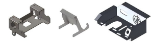
The typical sequence runs as follows:
- Design. The flat pattern is developed with bend allowances and corner reliefs.
- Cutting. Laser, punch, or waterjet removes the outline and the features.
- Forming. Press brakes bend the flat part into its 3D shape.
- Joining. Welding, fasteners, or adhesive assemble the formed parts.
- Finishing. Powder coat, plating, or anodizing protects and colors the surface.
Cutting: Choosing Between Laser, Punching, and Waterjet
The cutting operation sets the outline, the holes, and the edge quality, and the choice follows the geometry and the quantity. Laser cutting is tool-free and flexible, which makes it the right fit for complex contours, prototypes, and thin to medium sheet, with a clean edge and a small heat-affected zone. Punching is fast for standard holes and forms at volume; it can also create louvers and embosses in the same stroke, though the sheared edge carries some rollover and burr. Waterjet cutting handles thick plate and heat-sensitive materials with no heat input and a satin edge.
Laser programs also nest parts efficiently on the sheet, which keeps scrap low on mixed batches. The edge treatment matters for the next step: a burred punched edge may need deburring before forming or finishing, while a laser edge is usually ready to proceed. Many parts use more than one method, punched for the standard hole pattern and laser-cut for the complex contour. This mixed approach is common in industrial panels and fabricated assemblies, where the cost of each feature is matched to the process that produces it most economically.
Forming: The Bend That Makes It 3D
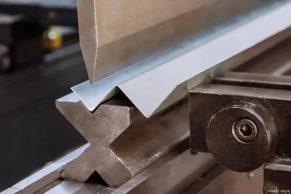
Forming is what turns the flat pattern into a part. A press brake holds the sheet between a punch and a die and bends it to the programmed angle, and the bend radius, the springback, and the material thickness set the result. The minimum bend radius depends on the material and thickness; bending too tightly cracks the sheet, and springback means the part must be over-bent to land the angle.
The design rules protect the forming step. Holes and features stay a minimum distance from bend lines so they do not distort during forming, internal corners get reliefs so the material does not tear, and the bend direction respects the material grain. As a practical rule, the inside bend radius should stay at or above the material thickness for most low-carbon steel, and tighter radii belong only to tempers and alloys that tolerate them. Hemmed edges, dimples, and stiffener ribs can be added during forming to make a thin panel behave like a thicker one, which is often cheaper than upgrading the gauge. The same part can be easy or impossible to form depending on these details, which is why the flat pattern review is part of the sheet metal tolerance conversation.
Materials: Naming the Grade and Thickness
Material selection follows the service environment and the cost. Mild steel covers enclosures, brackets, and frames at low cost and forms and paints easily. Stainless steel suits food, medical, and outdoor parts where corrosion resistance matters. Aluminum brings lighter weight and better thermal behavior for portable and heat-managed parts, at higher material cost. Copper and brass serve electrical and decorative parts on the strength of conductivity and appearance.
The thickness range matters as much as the grade. Sheet metal fabrication typically works from thin foil up to plate, and every material and thickness combination changes the bend radius, the cutting method, and the achievable tolerance. The drawing should name the grade, the temper, and the thickness, because “steel” is not a specification. Pre-coated and galvanized sheet changes the finish callouts, because welding over a coating damages it and the coating choice must be set before joining, not discovered after.
Joining and Finishing
Joining assembles the formed parts. Welding is strong and permanent, suited to frames and enclosures; fasteners allow disassembly, with PEM inserts and self-clinching hardware for repeated service; and adhesives join dissimilar materials without heat. The joining method affects the finish, because weld seams need grinding and paint, so the assembly sequence should be planned in the design, not discovered at the bench.
Finishing is part of the part. Powder coating is the standard durable finish for steel, anodizing suits aluminum, and plating or passivation suits stainless. Finishing cost is driven by surface preparation and masking: weld seams need grinding, sharp edges need radius, and threaded inserts may need masking before coating, so the drawing should note which areas are functional and which are coated. The finish protects the material and sets the appearance, and it should be specified against the service environment. A part designed without the finish is not a finished design, and a finish added after the fact is usually a rework.
Tolerances and Inspection: What the Process Can Hold
Sheet metal tolerances are set by the process, not by the machinist’s expectation. Cut features, laser-cut or punched holes and profiles, hold tighter tolerances because the cutting process is repeatable. Bent dimensions vary more, because springback and material thickness variation affect every bend. Where a bend-to-bend dimension matters for assembly, the drawing can call it out and the fabricator can compensate in the flat pattern; over-specifying every dimension, by contrast, inflates inspection without improving the fit. Mark the features that matter for assembly and confirm their tolerance with the fabricator before tooling or cutting begins.
Inspection follows the same logic. The mounting pattern, the openings, and the mating edges are the critical features, and the fabricator should measure them with calibrated equipment against agreed datums. A certificate of conformance without measurement data leaves the fit unproven, and the first article is where the tolerance story is verified. For parts with a mix of cut and formed features, the inspection plan follows the function, not the operation count. Where the drawing or the measurement method needs a common reference, standards such as those maintained by NIST measurement and standards guidance provide the vocabulary for specifying thermal cutting quality and general tolerances.
Design for Fabrication
The design rules that protect fabrication are few and important. Holes and cutouts stay a minimum distance from bend lines, internal corners get reliefs, and the bend radius follows the material and thickness. The flat pattern review catches these details before cutting, when they are free to fix. Enclosure design adds the assembly logic: datum faces, fastener patterns, gasket flanges, service access, and a disassembly plan. The same loop covers the assembly: the fastener type, the service access, and the disassembly plan are part of the design, because an enclosure that cannot be serviced is a design defect regardless of how it fabricates. A part designed for the flat pattern and the assembly sequence fits the first time; one that is not costs rework. If you are comparing routes for a new part, the article on 3D printing versus CNC machining helps explain when fabrication wins and when it does not.
Capabilities and Limits
Sheet metal fabrication produces light, strong parts at low cost, with tolerances that are looser than machining because bending introduces springback and material variation. The geometric limits are clear: the process cannot produce molded detail, tight machined tolerances, or internal cavities, and the thickness and bend behavior constrain the features. The cost advantage of fabrication comes from converting a sheet into volume: a bracket that would take lengthy machining time can be punched and bent in minutes, but the flat pattern must be efficient, because scrap is part of the price. Machining produces tighter tolerances in thicker sections; molding produces complex detail at volume; fabrication wins for enclosures, brackets, and structures where flat sheet and bends carry the design. The three routes are complementary, and many products use all of them.
Frequently Asked Questions
What materials are used in sheet metal fabrication?
Mild steel, stainless steel, aluminum, and copper or brass cover the common range. The grade and thickness change the bend radius, the cutting method, and the tolerance, so the drawing should name both rather than a generic material name.
What tolerances can sheet metal fabrication hold?
Looser tolerances than machining, because bending introduces springback and material variation. Cut features hold tighter tolerances than bent features, so the drawing should mark the dimensions that matter for assembly and confirm them with the fabricator.
When is sheet metal fabrication better than CNC machining?
When the part is an enclosure, bracket, chassis, or panel that can be folded from flat sheet, and the quantity does not justify machining time. Machining wins for thicker sections and tighter tolerances; fabrication wins where flat sheet and bends carry the design.