

The gap between a drawing and a part is usually a gap in definition, not a gap in skill. A dimension means nothing until its units, its coordinate and datum system, its tolerance basis, and its standard are stated. Misreading a millimeter as an inch, or a positional tolerance without the datum, produces parts that are technically machined and functionally wrong. This article explains how to communicate dimensions, units, standards, and callouts so the shop machines what the drawing intends.
State the Units Explicitly
The drawing title block should name the unit: millimeters, inches, or both, with a clear indication of which is authoritative. When both appear, a misplaced decimal or missing conversion changes everything. Include the unit with the dimension where the drawing standard allows, and confirm the setting with the shop before machining starts.
General Tolerances and the Standard
Un-dimensioned tolerances follow a standard, commonly ISO 2768 or a company general tolerance block. State which standard and which tolerance class apply, because “general tolerance” without a basis is a claim no one can verify. The general tolerance covers unspecified features; critical features still need their own explicit callouts.
GD&T and Datums
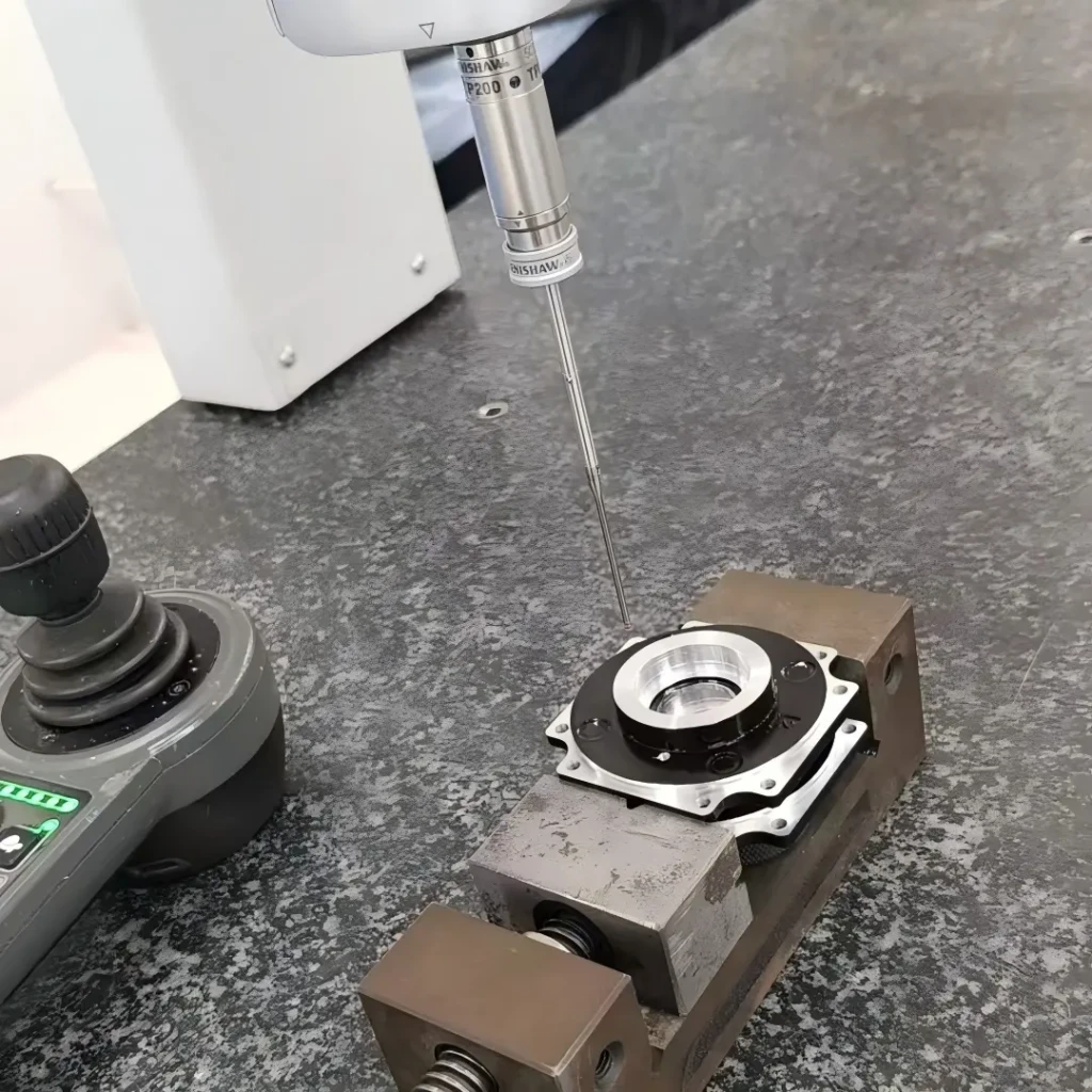
Geometric dimensioning and tolerancing (GD&T) controls form, orientation, location, and runout against a datum frame. The key is the datum: the part is measured the way it is held, so the datums should reflect assembly and inspection reality, not an arbitrary CAD origin. Call out position, flatness, runout, and profile with their datums and the standard (for example ASME Y128.5 or ISO GPS), and confirm the shop measures to the same datum structure.
Surface Finish Callouts
Surface finish needs a roughness value and a standard, e.g., an Ra under ASME B46.1 or ISO 4287. A mirror-polish instruction is not a spec. State the roughness, which surfaces it applies to, and whether the value is measured before or after finishing. The measurement matters: the same surface can read differently depending on the tool, cutoff, and probe.
Material, Coating, and Condition
The drawing should name the material grade and condition (such as 6061-T6, 304 annealed, 17-4 H900) and any coating or finish. A callout and material must be consistent with the standard the drawing cites, and tolerances must account for finishing thickness where coating applies.
Threads, Fits, and Special Callouts
Threads need the standard and class: naming a thread without the standard or fit class invites interpretation. Press-fit, slip-fit, and clearances should reference the fit system (ISO 286) with the tolerance letters. Every specialized callout that affects function belongs on the drawing or in the note with its standard.
A Drawing That a Shop Can Quote and Inspect
- Units stated in the title block, with one authoritative unit.
- General tolerance standard and class.
- Explicit dimensions with units on critical features.
- GD&T with datums and the standard used.
- Surface finish with a roughness basis.
- Material grade, condition, finish, and applicable standards.
- Threads, fits, and special callouts with their standards.
The Bottom Line
Communicating dimensions is about being interpretable by the persons who machine, inspect, and assemble. Name the units, the standards, the datum, the finish basis, and the material condition, and the drawing becomes a definition rather than a hope. The few minutes spent on callouts save the argument, the rework, and the part that machined perfectly but was the wrong part.
Note: standard interpretations vary by jurisdiction, confirm applicable versions with the drawing and the customer, and surface finish limits depend on the geometry and process.