

A drawing notes “M6 thread, 10 mm deep,” and the machinist has to guess whether that means 10 mm of full thread, 10 mm to the tap point, or 10 mm of engagement for a screw that may not even be M6 by the drawing’s other callouts. The resulting part either strips in assembly or costs extra because the hole was over-deepened “to be safe.” Thread callouts are compact codes that pack size, pitch, fit class, and depth into one line, and every missing element is an ambiguity the shop resolves with its own assumptions. Metric, Unified inch, and pipe threads each have their own logic, and reading them correctly is a drawing skill with direct cost consequences.
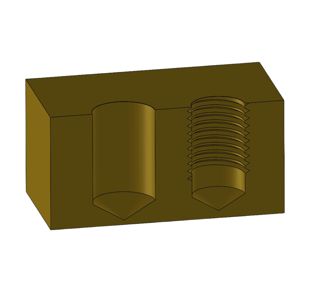
Thread callouts carry size, pitch, class, and depth
Every thread callout carries the nominal size, the pitch or threads per inch, the fit class, and the extent of the thread. A metric callout such as M6 × 1 means a 6 mm thread with a 1 mm pitch; a Unified callout such as 1/4-20 UNC-2B means a quarter-inch thread at 20 threads per inch, Unified Coarse, class 2, internal. The depth and the number of full threads should be separate and explicit, because “thread 10 mm deep” and “thread through” are different requirements, and a blind hole needs both a hole depth and a full-thread depth.
Omitting the class is the most common error. The class defines how tightly the thread fits its mating part, and it changes the tap size, the inspection gauge, and the plating allowance. A drawing that says “M6 × 1” without a class leaves the shop to choose the internal class — 6H is the common internal choice, while 6g is an external class for the screw, not an alternative for a tapped hole. Write the internal class explicitly (for example “M6 × 1 – 6H”) so the part, the gauge, and the coating allowance all reference the same fit.
Metric and Unified systems write the same contract differently
Metric threads are specified by pitch in millimeters; Unified threads by threads per inch plus a series code: UNC for coarse, UNF for fine, UNEF for extra fine. Fine pitches give more adjustment and hold better on thin walls; coarse pitches tolerate dirt and are faster to tap. Fit classes follow the same logic in both systems: metric tolerance is defined by ISO 965 with internal classes such as 6H and external classes such as 6g, while Unified threads follow ASME B1.1 with classes from 1 (loose) to 3 (tight), class 2 being the common general-purpose choice. Pipe threads follow ASME B1.20.1 for NPT. Write the class from the correct system for the thread form; an internal tapped hole carries an internal class such as 6H, and the mating screw carries the matching external class.
| System | Example | What each part means |
|---|---|---|
| Metric | M6 × 1 – 6H | 6 mm nominal, 1 mm pitch, 6H internal class |
| Unified | 1/4-20 UNC-2B | 0.25 in nominal, 20 TPI, coarse, class 2 internal |
| Pipe | 1/8-27 NPT | 1/8 in pipe size, 27 TPI, tapered pipe thread |
Write the callout in one system and do not mix units in the same feature. A drawing that mixes metric threads with inch-dimensioned mating parts is a source of expensive confusion, and the inspection gauge will not resolve a callout the shop had to interpret.
Pipe threads seal; fastening threads fit
Pipe threads are tapered and designed to seal, not just to fasten. NPT threads seal by interference between the tapered male and female threads, usually with sealant or tape; NPTF is a dry-seal variant. The nominal size refers to the pipe size, not the thread’s major diameter, which surprises designers who expect inch numbers to mean what they say. A 1/8 NPT port is physically much larger than 1/8 inch across the thread.
If the application is a pressure seal, specify the pipe-thread standard and the sealing method, and confirm the thread depth and port geometry with the supplier. Pipe threads in aluminum and other soft materials strip easily when over-tightened, so the port design, the recommended assembly torque, and the fitting material belong in the notes. Do not use a fastening-thread tolerance system on a pipe thread; the sealing behavior is governed by the taper and the standard.
Blind holes need both a full-thread depth and a hole depth
Thread depth callouts need the same care as diameter callouts. A tap does not cut full threads to the very bottom of a blind hole because the tap has a chamfer; the drawing should state the minimum full-thread depth and the minimum hole depth separately. A typical notation gives the full-thread depth and lets the shop add the tap clearance, but the requirement should be explicit when the engagement length matters for strength or sealing.
Counterbores and chamfers at thread entries protect the first thread and ease assembly; include them when a screw must sit flush or when the part is aluminum and prone to cross-threading. If the thread must accept a specific screw length, state the screw length and the required engagement rather than only the thread depth, because the two are related by the screw’s own tolerance.
How does coating change a thread callout?
Plating, anodizing, or coating adds material that changes the effective thread size. Internal threads can close in and fail to accept the mating screw, while external threads can grow beyond the class limits. The standard approach is to plan an allowance before coating or to mask the threads entirely. If the thread must be coated, the drawing should state the pre-coat size and the post-coat requirement so the shop chooses the right tap and the finisher measures the result.
The interaction is most visible on zinc-plated fasteners and anodized aluminum threads. A 6H internal thread tapped to size and then anodized may reject a 6g screw; the fix is tapping with allowance or masking. State the coating thickness and whether the thread is measured before or after coating, and the argument disappears at inspection. The CNC machining team can review thread callouts against the coating plan before quoting, and the drawing standards section on this site explains the full callout conventions.
The most common thread callout mistakes are worth naming because they are so expensive. Writing the pitch when the series already defines it, such as “1/4-20 UNC” with an added “× 20,” is harmless but noisy; mixing a metric screw with an inch clearance hole in the same assembly is not. Omitting the class, the depth, or the coating basis forces the shop to guess, and each guess has a cost direction: deeper holes cost cycle time, tighter classes cost tooling and inspection, and unplanned coating allowance causes rejects at the fit gauge. Another frequent error is specifying a thread on a thin wall without checking the wall can carry full threads, which leaves a thread that strips at a fraction of its nominal strength. Naming the mating part and the engagement length on the drawing prevents this, because the machinist can then confirm the wall and the depth together. Finally, drawings that use one thread standard for the part and another for the hardware create silent mismatches that pass dimensional inspection and fail at assembly. Keep the drawing, the hardware BOM, and the coating notes on the same standard, and review the three together before release rather than approving them separately.
Thread inspection is the other half of the callout, and it deserves as much care as the drawing. Go/no-go gauges verify the pitch diameter and the fit class quickly, but they do not verify depth, runout, or the condition of the thread form at the bottom of a blind hole. If the drawing specifies a full-thread depth, the inspection should confirm it with a depth-measuring method, not with the go gauge alone; if the thread is coated, the gauge check should happen after coating or against the post-coat requirement. Thread runout and perpendicularity matter on sealing and precision features, and those callouts belong on the drawing when the function needs them, because a thread that gauges perfectly can still be tilted relative to the sealing face. When a thread fails, the report should separate the failure mode — size, depth, form, or position — so the fix targets the actual cause. The shop and the inspector should use the same gauge class and the same measurement basis; otherwise the part can pass one side and fail the other on the same feature.
Frequently asked questions
What does the “B” in a Unified callout such as 2B mean?
The letter designates internal or external: B means internal (the nut or tapped hole), and A means external (the screw or bolt). So 2A is an external class-2 thread and 2B is an internal class-2 thread. Matching A and B classes of the same number is the standard assembly; mixing classes changes the fit and should be a deliberate design choice.
Should the drawing specify the tap drill size?
No. The tap drill size is the shop’s process decision, and publishing it in the drawing can freeze a process that should vary with material, coating, and tooling. Specify the finished thread requirement — size, pitch, class, depth, and coating — and let the shop select the drill and tap that achieve it in the material.
Can a thread be specified in a soft material like aluminum or plastic?
Yes, but the callout should account for the material’s lower thread strength. Aluminum threads may need longer engagement, larger sizes, or inserts; plastic threads often use thread-forming screws with a different hole specification than cutting taps. Name the material in the drawing so the thread class and depth are reviewed against it.
Conclusion
Thread callouts are a contract between the drawing and the tap: size, pitch, class, depth, and coating must all be explicit, and pipe threads must be treated as sealing features, not fasteners. Write the full callout in one system, state the measurement basis before and after coating, and leave the process details to the shop. The part that assembles without argument is the one whose thread was specified the way it will be made.
If you are finalizing a drawing with threaded features and want the callouts checked against your coating and assembly plan, send the drawing to the 6CProto CNC team before quoting. A thread callout review takes minutes and prevents the most common first-article rejection in machined parts.