Michael Wang

Founder & Mechanical Engineer

As the founder of the company and a mechanical engineer, he has extensive experience in advanced manufacturing technologies, including CNC machining, 3D printing, urethane casting, rapid tooling, injection molding, metal casting, sheet metal, and extrusion.

Table Of Contents

CNC, computer numerical control, is a family of machines that follow programmed tool paths, and the family covers far more than the mills most people picture. Turning centers rotate the part against a stationary tool, machining centers rotate the tool against a stationary part, and the same control technology runs lathes, mills, multi-axis machines, grinders, electrical discharge machines, laser cutters, and waterjets. The machine type is chosen by the geometry and the material of the part, so understanding the family is the first step in reading a manufacturing quote. This guide classifies the main CNC machine types, the parts each one produces, and the selection logic that maps a part to a machine.

The Two Families: Rotate the Part or Rotate the Tool

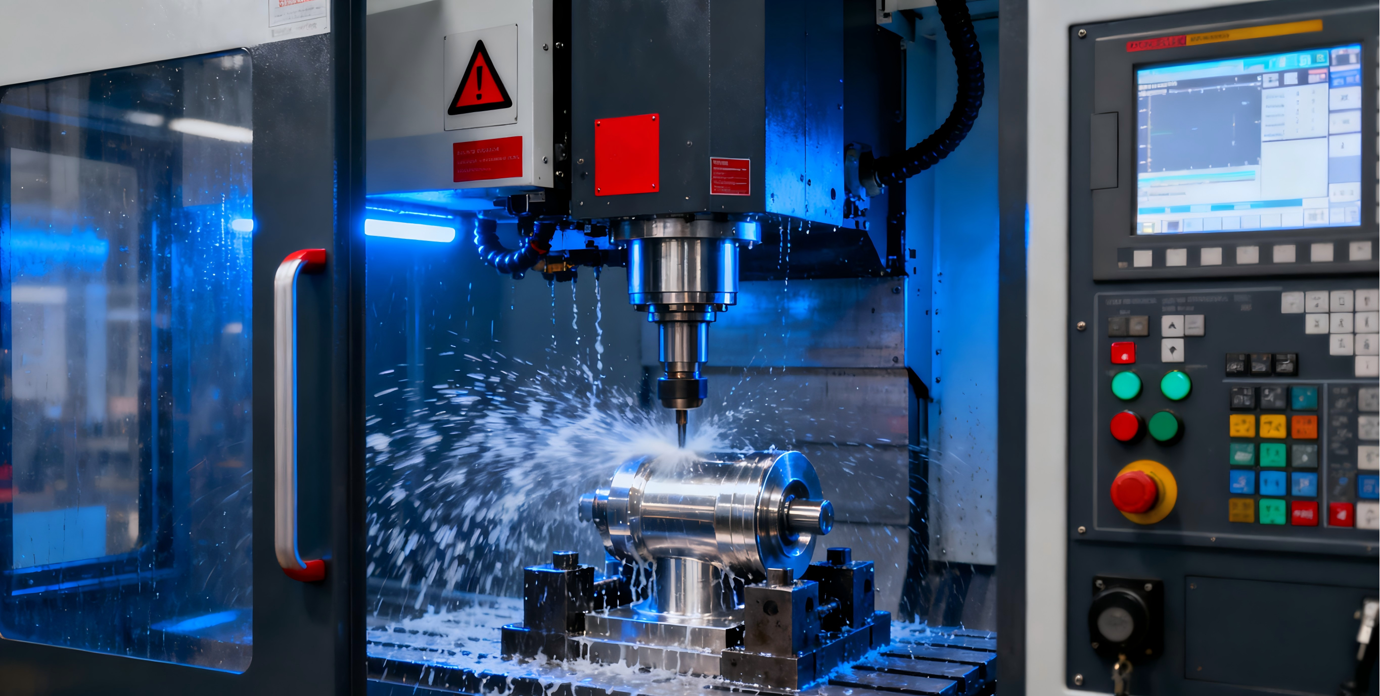
CNC machines split into two mechanical families. Turning machines rotate the workpiece and feed a stationary tool into it, producing cylindrical features: diameters, faces, bores, grooves, and threads around a centerline. Machining centers rotate the cutting tool and move it across a stationary part, producing prismatic features: flat faces, pockets, slots, holes, and contoured surfaces.

The distinction drives the quote. A shaft with critical diameters is a turning part; a housing with a pocket and a bolt pattern is a milling part; and a part with both is a turning center with live tooling or a turn-mill machine, which combines the two families in one setup. The first question in any machining conversation is which family the part's critical features belong to.

Machine family How it cuts Parts it produces
Turning centers Rotates the part Shafts, pins, bushings, fittings
Machining centers Rotates the tool Brackets, housings, plates, covers
Turn-mill centers Both, in one setup Rotational parts with cross-features
Multi-axis centers Added axes for complex geometry Impellers, molds, sculpted surfaces
Grinders Abrasive wheel Tight-tolerance bores and finishes
EDM Electrical erosion Hard materials, sharp corners, molds
Laser and waterjet cutters Cutting sheet and plate Flat parts, profiles, sheet metal

Machining Centers and Multi-Axis Machines

The vertical machining center is the workhorse for prismatic parts: the spindle is vertical, the part is clamped on the table, and the tool moves in X, Y, and Z. Three-axis machines cover the majority of brackets, housings, and plates. Adding a rotary axis or a tilting head creates four- and five-axis machines, which reach undercuts, cut contoured surfaces, and reduce setups by presenting multiple faces to the tool without re-fixturing.

The multi-axis decision is an economics question, not a capability contest. A part that fits in one three-axis setup is cheaper on a three-axis machine; a part with undercuts or contoured faces that would need multiple setups is often cheaper on a five-axis machine despite the higher hourly rate. The setup count is the best predictor, which is why the DFM review counts setups before choosing the machine.

Turning Centers and the Turn-Mill Boundary

Turning centers produce rotational parts with high concentricity, because features cut in one setup share the rotation axis. The machine range spans simple two-axis lathes, turning centers with live tooling that can cross-drill and mill, and Swiss-type machines that feed bar through a guide bushing for small, long parts. The choice follows the geometry: short stiff parts on a conventional lathe, small long parts on a Swiss machine, and mostly cylindrical parts with a few cross-features on a live-tooled center.

The turn-mill boundary is the ratio of milled work to turned work. When the milled content is small, the turning center with live tooling completes the part in one setup; when the milled content dominates, the part belongs on a machining center, because dedicated milling is faster. The drawing should group features by process so the quote reflects the real route.

Grinding, EDM, and the Finishing Machines

The finishing machines handle what cutting cannot. Grinders use an abrasive wheel to produce the tightest tolerances and finest finishes, especially on hardened steel bores and bearing surfaces. EDM, electrical discharge machining, erodes material with sparks from a shaped electrode, cutting hardened steel, sharp internal corners, and deep narrow slots that milling cutters cannot reach, at the cost of speed and a re-cast surface layer that needs finishing.

These machines appear in production when the part's hardness, tolerance, or geometry rules out milling and turning. A hardened die cavity with small corner radii is EDM; a precision bore in a hardened shaft is grinding. The hardness and the finish requirement on the drawing are what send the part to the finishing machine, so both belong in the callout.

Laser Cutters, Waterjets, and the Sheet Family

The sheet family cuts flat material. Laser cutters melt and vaporize metal with a focused beam, cutting thin sheet fast and precisely; waterjets erode with abrasive water, cutting thick and heat-sensitive materials without a heat-affected zone. Punch presses stamp holes and form features in sheet metal, and press brakes bend the flat parts into shapes. Together they produce brackets, enclosures, chassis, and panels.

The sheet family is selected by thickness, material, and the edge requirement. Thin metal parts default to laser or punch; thick plate, reflective metals, and heat-sensitive materials go to waterjet; and formed features need the punch or a press. The machine choice is a material and geometry decision, not a preference.

Selection Logic: Map the Part to the Machine

Work through the part in order:

  1. Identify the critical features: are they cylindrical, prismatic, or both?
  2. If cylindrical, choose a turning center, and a Swiss machine for small, long parts.
  3. If prismatic, choose a machining center, and multi-axis for undercuts or contoured faces.
  4. If both, choose a turn-mill center, and move the milled content to a dedicated mill when it dominates.
  5. If the material is hardened or the tolerance is beyond cutting, choose grinding or EDM.
  6. If the part is flat sheet, choose laser, punch, or waterjet by thickness and edge.

The logic is a filter: most parts fall into one machine, and the exceptions define the setup count and the cost. A CNC machining partner that runs turning, milling, and multi-axis work can quote the same part across the family, and the DFM review matches the machine to the part's critical features.

The machine choice also interacts with the material. Hard metals, titanium, Inconel, and hardened steel, need rigid machines and slow, controlled cutting, while soft materials, aluminum and brass, run fast on standard equipment. The material and the machine should be matched in the quote, because a shop that runs aluminum production may not have the rigidity for Inconel, and the capability question belongs in the DFM review before the order.

The same logic applies within a family: a five-axis machine with a large envelope and a five-axis machine for small precision work are different assets, and the quote should name the machine class, not just the axis count.

Conclusion

CNC machines are a family organized by how the cut happens: rotate the part for cylindrical features, rotate the tool for prismatic features, add axes for complexity, and use grinding, EDM, or cutting for what the main processes cannot do. Map the part's critical features to the machine family, count the setups, and choose the machine that produces the part at the lowest cost. The machine type follows the geometry, which is why the drawing and the DFM review decide it together.

FAQs

What are the main types of CNC machines?

Turning centers, machining centers, turn-mill centers, multi-axis machines, grinders, EDM machines, laser cutters, waterjets, and punch presses. The family is organized by how the cut happens, and the machine is chosen by the part's critical geometry.

What is the difference between a lathe and a mill?

A lathe rotates the workpiece against a stationary tool and produces cylindrical features; a mill rotates the tool against a stationary part and produces prismatic features. Parts with diameters, faces, and threads are turning parts, while parts with pockets, slots, and flat faces are milling parts.

When should I use a 5-axis machine?

When the geometry has undercuts or contoured surfaces that would need multiple setups on a three-axis machine, or when the part must be presented to the tool from several angles without re-fixturing. The setup count is the best predictor, so the multi-axis decision is an economics question.

What is EDM used for?

EDM cuts materials and geometry that milling cannot: hardened steel, sharp internal corners, and deep narrow slots. It uses electrical erosion instead of cutting forces, at the cost of speed and a re-cast surface layer that needs finishing.

Sources

Related