

A hypothetical 0.5° angular error produces about 0.87 mm of height difference over a 100 mm horizontal reach. That geometric example shows why a small weld-related rotation can matter at a mounting interface. Sheet metal welding fabrication needs a controlled route and a defined final measurement state, especially when a cover, seal, or mating component depends on alignment.
Why thin sheet distorts
Specify sheet metal welding fabrication through the material, joint geometry, required weld, final dimensional state, critical interfaces, applicable acceptance rules, and inspection evidence. Review fit-up, support, sequence, and finishing with the welding engineer. Control the delivered geometry and weld quality separately rather than assuming an attractive bead or a clamped assembly proves both.
Localized heating and cooling do not affect the whole panel uniformly. TWI’s explanation of welding distortion describes how thermal expansion and contraction can create stresses and permanent deformation. Thin-sheet geometry also makes the final shape sensitive to support and joint arrangement.
Identify the form of movement that threatens function: angular change, a bowed panel, shifted mounting features, or a mismatched gap. The opening calculation is only geometry: h = L tan θ, so 100 × tan 0.5° ≈ 0.87 mm. It does not predict how much a particular weld will distort or establish a 6CProto tolerance.
Process and joint design levers
Begin with the required joint rather than a universal preference for MIG or TIG. Material, thickness, access, deposition needs, finish, and qualification requirements influence process selection. The welding engineer must review the proposed method and procedure against the actual assembly.
TWI’s design guidance discusses weld placement, deposited volume, and balanced welding. Apply those principles while preserving required joint strength and function. A continuous sealing seam cannot become intermittent solely to reduce distortion, and reducing weld size below the approved design is not a valid process improvement.
Implement the review in order: confirm fit-up and access, identify distortion-sensitive interfaces, agree support and sequence, make a representative sample, and inspect the released result. If a process change affects the joint or required qualification, obtain approval before using it for production.
Table: inspection of weldments
Make the inspection plan answer both geometric and joint-quality questions. Specify the condition in which the assembly is accepted, including whether it is released, mounted to a defined reference, or restrained as part of an agreed method. A fixture should not conceal an unacceptable free-state result.
| Requirement | Definition needed | Evidence to agree |
|---|---|---|
| Mounting interface | Datums, position, form and inspection state | Relevant dimensional results |
| Weld geometry and appearance | Required joint and applicable criteria | Defined visual and dimensional inspection |
| Internal or surface discontinuities | Applicable method, coverage and acceptance | Specified examination record where required |
| Sealing function | Test boundary, conditions and criterion | Agreed test result, separately specified |
| Finish after welding | Permitted blending, cleaning and coating | Finished sample and final interface check |
AWS D1.3’s public scope addresses specified sheet-steel applications. Select a governing code only when its scope fits the material and project. Do not extend a sheet-steel code automatically to aluminum or every stainless assembly.
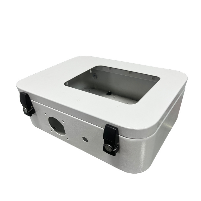
When hardware beats welding
Consider removable hardware, formed features, or another approved joint where the product does not require a welded connection. Avoiding a weld can remove one source of thermal distortion, but it introduces its own load transfer, fastener access, retention, and service considerations.
Compare the complete interface. A screwed cover can provide access, while a permanent structural or sealed seam may require a different solution. A change in joining method can affect continuity, leakage, stiffness, and the mounting arrangement even when the visible enclosure dimensions remain the same.
Make that decision before finalizing the drawing. The fabricated-assembly review should identify which joints are essential and which alternatives can be assessed. Require the responsible designer to approve the chosen arrangement and its acceptance criteria.
RFQ notes
Provide the material grade and condition, thickness, model, component and assembly drawings, weld requirements, quantity, finish, critical interfaces, and required records. Identify supplied components and any material or process restrictions. State whether a proposed sequence needs formal approval.
ASME Y14.5 provides geometric communication rules under the selected drawing convention. Define the final assembly’s functional references and acceptance state. A tightly controlled individual panel does not alone establish the relationship between mounting points after joining.
Ask the quotation to identify fixtures, sample development, any straightening, finishing, and inspection. Agree whether machining after welding is needed for a critical interface and whether it is included. Do not leave correction work as an unpriced assumption discovered only after the sample fails to fit.
FAQ
These questions address specification details that should be settled before sample approval.
Does stronger clamping guarantee the released assembly will remain flat?
No. A restraint can hold geometry during welding while the assembly still moves after release or retains significant stress. Define the accepted state and review the fixture, sequence, material, and procedure together. Inspect the result in the required condition.
Is TIG always the lower-distortion choice for thin sheet?
No. Process selection depends on the material, thickness, joint, access, deposition conditions, and approved procedure. Compare the actual proposed routes and representative results. A process name alone does not establish heat distribution or the final geometry.
Can distortion control justify reducing a specified weld?
Only through an approved design change that still meets the joint requirements. Required size, extent, strength, sealing, and other functions must remain satisfied. Review a proposed reduction with the responsible engineer and preserve the approved specification in the manufacturing instructions.
Related process selection notes
TWI’s technique discussion identifies weld size, joint geometry, and balanced deposition as relevant to angular distortion. Let the approved procedure connect those considerations to the actual part. A generic sequence copied from a different assembly is weak evidence.
Review the offered stainless-steel grade or aluminum grade and associated finishing requirements separately. The material name, cleanliness, joining procedure, and post-weld surface condition all need to match the order.
Use first samples to close the meaningful uncertainties: fit-up consistency, access, released shape, joint acceptance, and finish. Preserve the approved material, sequence, fixture assumptions, and inspection method for repeat manufacturing. A cosmetic photograph cannot replace those records.

Internal links and next steps
Bring the weld plan into the sheet-metal fabrication scope before comparing complete quotations. Include cutting, bending, joint preparation, welding, finish, and final inspection. Identify what is included, proposed for review, or excluded.
Return to the angular-error example during the design review. Decide which interface actually limits acceptance and specify its relationship to the mounting references. The aim is not an unsupported promise of zero distortion; it is a demonstrably acceptable joint and delivered assembly.
Request a 6CProto weldment review with the joint, final geometry, and inspection requirements. Approve the representative result and documented route before releasing the planned production order.