

Explore Sheet Metal Design, Materials & Assemblies
A prototype assembly can meet its dimensions in the welding fixture and spring out of position as soon as the clamps open. Adding more clamps may improve the restrained reading while making removal and process diagnosis harder. The fixture needs a defined locating purpose, not simply the greatest possible restraint.
A sheet metal prototype weld fixture should connect the cut and formed parts to the final assembly requirements. Identify the references that establish position, the supports that carry load and the clamps that retain contact. These roles can use different components and should remain distinguishable during development.
The first trial should reveal whether the parts seat repeatably, whether the weld can be completed and whether the assembly can be removed without force. Only then can a measured result be related usefully to a fixture revision.
For manufacturing context, see sheet metal fabrication. This guide focuses on prototype fixture decisions and their evidence. It does not replace the welding procedure or assume that geometry held under maximum restraint represents the finished product after release.
Datum features on the cut and formed parts
Locate from features that represent the assembly intent.
Identify the primary references and their condition after cutting and forming, then separate locating contacts from supports and clamps so each component has a defined role in positioning.
A laser-cut edge can be convenient but may not control the finished interface. A formed flange can represent the function yet vary in angle or local shape. Review which features remain stable enough to locate and which need clearance to accommodate permitted part variation.
Carr Lane’s locating and clamping principles distinguishes referencing, repeatability and the roles of locating and clamping. Apply those principles to the actual thin-sheet geometry rather than treating a standard contact count as a universal fixture recipe.
Avoid making several imperfect features compete to define the same position. If two holes establish location, review how the second contact accommodates their permitted spacing variation. A part that requires force to seat may be revealing redundant constraint, a dimensional issue or debris. Diagnose that condition before the clamp converts it into an apparently repeatable but strained assembly.
Access for weld sequence and removal
Check the operation as a changing assembly. A torch or electrode may reach the first weld but become obstructed after a return panel or neighboring clamp is installed. Model the planned order with the real tool envelope and the interfaces that require observation.
Removal deserves its own review. A completed weldment can enclose a locator or shrink against a fixture feature. A successful welding cycle is incomplete if extracting the assembly bends it or requires an unplanned cut in the fixture.
TWI’s distortion and restraint guidance discusses fixture use and the need to remove the finished fabrication. It also explains that restraint can introduce residual stresses, so added rigidity should be judged against its consequences rather than treated as an automatic improvement.
Show clamp release, retractable locators and the extraction direction. Check access to cleaning and spatter-prone contact areas. For a fabricated assembly, identify any temporary fastening or tacking step that changes access. The approved sequence should explain how the fixture remains usable from loading through final release.
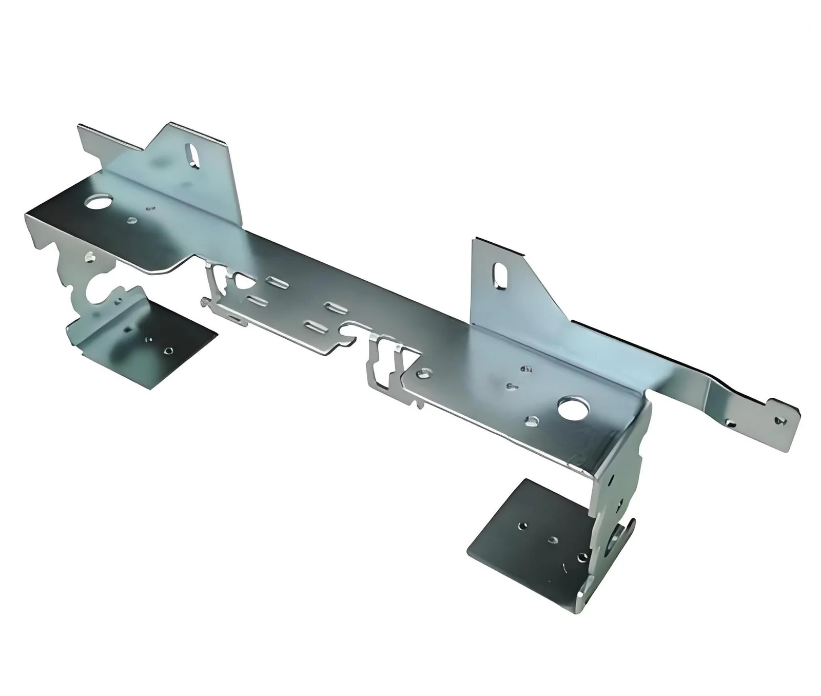
Replaceable locating features
Prototype fixtures benefit from controlled adjustment when the product is still evolving. Replaceable pins, pads or stops can make a local revision practical without rebuilding the whole base. Their interfaces must still locate repeatably and preserve an identifiable setup.
Give replaceable components part numbers or revision identities. A shim added during a trial changes the locating condition, even when it is temporary and inexpensive. Record its thickness, location and purpose rather than allowing an undocumented stack to become the production definition.
Protect the contacts that establish position from wear, spatter and damage during loading. Consider cleaning access and inspection of the contact surfaces. A sophisticated fixture cannot remain repeatable when its reference surfaces accumulate material that changes seating.
Use adjustment to test a hypothesis, not to hide inconsistent incoming parts. If different blanks need different settings, investigate which feature is changing and whether it lies within the released requirement. Stabilize the reference concept before locking the fixture configuration. The goal is an understandable locating system that supports a repeatable assembly, not a collection of compensations whose effects cannot be separated.
Check free state geometry after unclamping
Measure the accepted product in its specified condition. If the drawing requires free-state geometry, inspect after the relevant clamps and temporary restraints have been removed. A fixture-state check remains useful process evidence, but it answers another question.
Record the release sequence during development. Opening one clamp can redistribute contact and reveal where the assembly was being held against its natural shape. Observe that behavior without treating every movement as a defect; the drawing requirement determines the consequence.
TWI’s joining-process simulation overview identifies clamping, tack welds and sequence as variables affecting distortion predictions. This supports reviewing them together, while its discussion of assumptions cautions against treating a model as guaranteed fixture performance.
Compare the same functional features before and after release. Use consistent references and support so the difference is attributable to the assembly state rather than an inspection change. If the part moves out of requirement, investigate the locating concept, restraint and welding route before adding clamps. Stronger restraint can make the in-fixture result look better without delivering the required released shape.
Locators, supports and access on the fixture drawing
The fixture drawing should explain how the parts seat and what each contact controls. Use a clear section and contact map rather than showing a collection of clamps with no reference hierarchy. Distinguish product datums from convenient fixture construction references.
The matrix below connects fixture elements with their verification. It deliberately supplies no universal clamp forces or locating clearances; those depend on the parts and operation.
| Element | Purpose | Trial observation |
|---|---|---|
| Locator | Establish defined position | Repeat seating without forced fit |
| Support | Carry local reaction | No unsupported clamping deformation |
| Clamp | Retain intended contact | Stable contact and accessible release |
| Retractable feature | Enable loading or extraction | Clearance through full sequence |
The ASME drawing framework supports geometric references and requirements on the assembly. It does not determine a welding fixture’s contact arrangement. Use the assembly requirements to assess whether the proposed fixture controls the right relationships and leaves permitted variation somewhere to go.
Repeat loading before committing the weld sequence
Use unwelded loading trials to establish whether the parts seat consistently. Load, locate, clamp and release representative blanks while observing contact and final reference positions. This separates a locating problem from movement introduced by welding.
For a hypothetical two-flange bracket, mark the contacts that establish the mounting face and hole relationship. Check whether a change in bend angle causes one locator to lift or forces the flange against a competing stop. Revise the contact concept if permitted variation prevents natural seating.
Then introduce the proposed tacking and welding stages. Preserve the fixture configuration and record any deliberate adjustment. A dimensional improvement after changing both the locators and the weld sequence cannot be attributed confidently to either change alone.
NIST’s measurement-process variability discussion provides context for separating repeated-setup variation from differences between parts. Use that distinction when evaluating fixture repeatability. Several readings on one unmoved part do not demonstrate repeated loading, and several different parts do not isolate what the loading operation contributes to the observed spread.
Acceptance after welding and fixture release
Define fixture acceptance and assembly acceptance separately. The fixture needs to support repeat loading, process access and removal. The welded product needs to meet its own joint and geometric requirements after the specified operations. Neither decision can be inferred automatically from the other.
Inspect functional interfaces rather than only convenient outside dimensions. A bracket can retain its overall envelope while mounting holes or mating faces change relationship. Identify the relevant datum scheme and any specified restrained condition in the measurement record.
Renishaw’s metrology-fixturing overview emphasizes repeatable inspection setups. An inspection fixture can therefore be useful, but it must not force a flexible assembly into conformity when the acceptance condition is free state.
NIST’s uncertainty-analysis guidance explains why measurement quality matters to the decision. Apply that reasoning when comparing small movements after a locator change. State the supports, release stage and measurement limitations. A successful trial should demonstrate the accepted assembly condition with a method capable of distinguishing it, rather than merely report stable coordinates while the fixture holds the part.
Fixture scope and revision evidence for quotation
Supply the assembly CAD, component drawings, final datum scheme and planned joining sequence with the fixture request. Include expected prototype quantities, loading access and any features likely to change during development. Those details influence whether replaceable or adjustable elements are worthwhile.
State the intended deliverable. A temporary prototype aid, an approved production fixture and a fixture used to support qualification can require different documentation and evidence. Identify the acceptance owner and the trials needed before release.
Request the configuration record, contact map, access review and representative assembly results. Include the removal sequence and any maintenance needed to keep locating surfaces usable. Changes made during development should remain visible in the final drawing rather than surviving only as workshop adjustments.
Use the standards and tolerances reference as discussion context, with the actual product documents controlling acceptance. Define how future component or weld-sequence changes will trigger review. A fixture is useful for repeat work only while its locating concept and process assumptions still match the released assembly.
FAQ
Can the welding fixture also be used for final inspection?
It may support some checks if the method and acceptance state are appropriate. Review whether the fixture restrains the features being measured and whether it references the product datums correctly. A fixture-state check cannot establish free-state geometry without a separate justified method. Document the inspection role explicitly, including supports, clamps and limitations. Do not assume that a tool capable of holding the part accurately also demonstrates the released assembly condition.
Should every flexible flange have a locating stop?
No universal rule applies. A flexible flange may need support without an additional locator that competes with the intended reference scheme. Review its function, allowed variation and load during welding. A stop that forces every blank into the same position can conceal strain or a dimensional problem. Choose contacts by their defined roles and confirm their effect during repeated loading and after release, rather than maximizing the number of contacts.
Can a prototype fixture be transferred directly to production?
Only after reviewing whether its configuration, durability, process controls and evidence suit the production duty. Prototype adjustments may have been acceptable for development while remaining undocumented or operator dependent. Capture the final locating concept, replaceable features, sequence and inspection requirements. Demonstrate repeat loading and representative released assemblies under the proposed production conditions before treating the successful prototype aid as an approved production tool.
Conclusion
A useful prototype fixture makes location and process behavior understandable. Establish the product references, retain contact with suitable support, preserve welding and removal access, and measure the released assembly. Added restraint is valuable only when it helps deliver that accepted condition.
Use loading trials to separate fixture behavior from part variation, then introduce welding in a documented sequence. Keep local adjustments and replaceable-feature revisions identifiable. This turns a successful prototype into evidence that can support the next build instead of a one-off result dependent on hidden shims and operator force.
For a fixture and assembly review, upload the assembly CAD, datum requirements and planned weld sequence. Include loading, tool-access and removal constraints so 6CProto’s DFM review can assess the complete fixture duty and its verification scope.
{“@context”: “https://schema.org”, “@type”: “FAQPage”, “mainEntity”: [{“@type”: “Question”, “name”: “Can the welding fixture also be used for final inspection?”, “acceptedAnswer”: {“@type”: “Answer”, “text”: “It may support some checks if the method and acceptance state are appropriate. Review whether the fixture restrains the features being measured and whether it references the product datums correctly. A fixture-state check cannot establish free-state geometry without a separate justified method. Document the inspection role explicitly, including supports, clamps and limitations. Do not assume that a tool capable of holding the part accurately also demonstrates the released assembly condition.”}}, {“@type”: “Question”, “name”: “Should every flexible flange have a locating stop?”, “acceptedAnswer”: {“@type”: “Answer”, “text”: “No universal rule applies. A flexible flange may need support without an additional locator that competes with the intended reference scheme. Review its function, allowed variation and load during welding. A stop that forces every blank into the same position can conceal strain or a dimensional problem. Choose contacts by their defined roles and confirm their effect during repeated loading and after release, rather than maximizing the number of contacts.”}}, {“@type”: “Question”, “name”: “Can a prototype fixture be transferred directly to production?”, “acceptedAnswer”: {“@type”: “Answer”, “text”: “Only after reviewing whether its configuration, durability, process controls and evidence suit the production duty. Prototype adjustments may have been acceptable for development while remaining undocumented or operator dependent. Capture the final locating concept, replaceable features, sequence and inspection requirements. Demonstrate repeat loading and representative released assemblies under the proposed production conditions before treating the successful prototype aid as an approved production tool.”}}]}