Michael Wang

Founder & Mechanical Engineer

As the founder of the company and a mechanical engineer, he has extensive experience in advanced manufacturing technologies, including CNC machining, 3D printing, urethane casting, rapid tooling, injection molding, metal casting, sheet metal, and extrusion.

Table Of Contents

Flatness is a story of stresses. A sheet-metal panel starts flat, and every process—cutting, bending, welding—adds stress that tries to pull it out of shape. The warped panel is not a mistake; it is the material responding to the process. Controlling flatness means managing the stresses: how the material is cut, how the bends are made, how the welds are sequenced, and how the part is straightened. This guide covers the sources and the controls.

Flatness Is a Story of Stresses

A flat panel is flat because the stresses in it are balanced. When a process adds or removes material unevenly, the balance breaks and the part warps. The warp is the material seeking equilibrium under the new stress state.

That framing explains why flatness control is process control: the cutting parameters, the bend sequence, the weld order, and the handling all affect the stress balance. The part that stays flat is the part whose processes were balanced.

Flatness problems start inside the sheet, not on the surface. The mill rolling, the coil, and the stored tension leave residual stress in the material; cutting, forming, and welding then release or rebalance that stress unevenly, and the panel moves. A truly flat part is the result of managing every step that touches the stress state.
The same sheet can produce two different flatness results depending on how the parts are nested. Cutting parts in a balanced pattern across the sheet keeps the residual stress distributed; cutting everything from one corner lets the remaining stress pull the parts that sit near the cut lines.
Flatness also drifts over time. A stressed panel can move between the shop floor and the assembly line, and a part that measured flat on Friday can measure bowed on Monday; the buyer should specify the measurement condition—supported, free-standing, or clamped—so the check is repeatable.

Cutting and Thermal Effects

Cutting introduces heat and removes material, and both affect flatness. Laser cutting heats the edge zone, and the thermal gradient can distort thin panels; the cut pattern removes material and shifts the stress balance. The effects scale with the panel size and the material.

The controls are process-side: cutting parameters, sequencing, and support. For thin large panels, the cutting strategy is part of the flatness plan.

The cutting order is a stress-balancing decision. The parts are cut in the sequence that keeps the sheet's stress even, and the skeleton and the parts are managed; the order is the cutting's balance. The buyer should discuss the cutting order with the supplier, because the flatness follows it. The order that is balanced is the one that is stable.

The cutting speed and the power are the heat's controls. The laser's parameters set the heat input, and the heat input sets the edge stress; the parameters are the cutting's thermal control. The buyer should confirm the cutting parameters with the supplier, because the flatness follows the heat. The parameters that are controlled are the ones that protect.

Thermal cutting adds heat to the stress story. The laser heats a narrow zone along the cut edge, and that zone contracts as it cools, pulling the panel edge; thin material and long cut lines are the most sensitive, which is why large thin panels are the classic warpage victims.
The cutting strategy can balance the thermal effect. Small parts can be cut in a sequence that keeps the sheet's heat even, and large parts can be tabbed or skeleton-cut so the panel is not fully released until the heat has stabilized; the nesting plan is part of the process quality.
Cutting parameters also matter at the edge. Speed and power set the heat input per millimeter, and a hot edge with a heavy heat-affected zone carries more residual stress; a shop that tunes the cutting parameters for the material and gauge is managing flatness before the first bend is made.

Bending and Springback Contribution

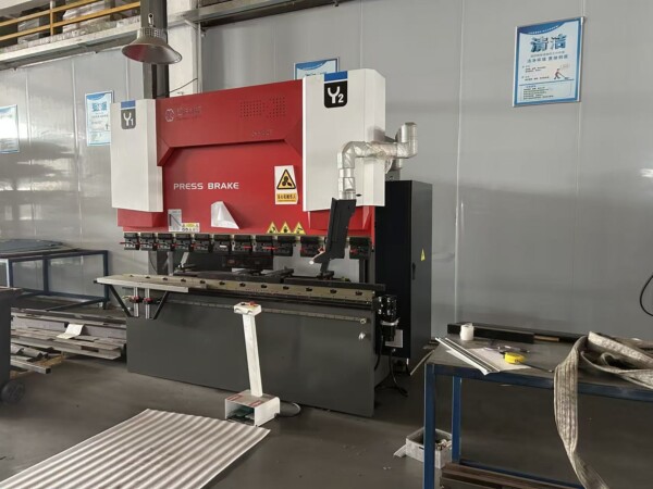
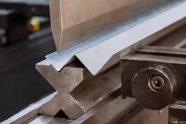
Bending forms the material and leaves residual stress. The bend creates a stress state that, combined with the panel's other stresses, can pull the part out of flat. Springback—the material's return after forming—is part of the same story.

The control is the bend design and sequence: symmetric bends, balanced tooling, and a sequence that keeps the stress state even. The flatness-critical part is designed and formed with the stress in mind.

A bend changes the stress state around the bend line. The outer fiber stretches, the inner fiber compresses, and the transition zone carries residual stress; when several bends are made in sequence, each one modifies the balance left by the previous one, and the panel can twist rather than stay flat.
Bend order and direction matter for flatness. Bending features that oppose each other can cancel distortion, while bending everything on one side of the panel can curl it; the process plan should sequence the bends to keep the stress state balanced across the part.
Springback is part of the same story. The material returns partway after forming, and the compensation applied in the tooling sets the final angle; a bend that is over-compensated on one flange can pull the panel out of plane even though the angle measures correct.

Welding Distortion and Control

Welding is the largest flatness risk: the heat shrinks the material at the weld, pulling the panel. The distortion depends on the weld length, the heat input, and the panel's stiffness. Welding a large flat panel is an exercise in distortion control.

The controls are weld sequencing, heat management, and clamping. The weld order and the fixturing decide how much distortion appears, and the straightening step corrects what remains.

The welding sequence is the distortion's control. The welds are placed and sequenced to balance the shrinkage, and the fixturing holds the part during the welding; the sequence is the distortion's management. The buyer should confirm the welding plan with the supplier, because the flatness follows it. The plan that is controlled is the one that is true.

The welding heat input is the distortion's driver. The amperage, the speed, and the pass sequence set the heat, and the heat sets the shrink; the input is the distortion's variable. The buyer should confirm the welding parameters, because the flatness follows the heat. The parameters that are managed are the ones that protect.

Welding is the strongest distortion driver in assembled sheet-metal parts. The weld pool heats a narrow zone, and the surrounding material resists its expansion and contraction; the result is shrinkage and distortion around every weld line, with the panel bowing toward the welded side.
The weld sequence distributes the shrinkage. Alternating welds, back-stepping, and balancing welds across the part let each weld's pull be offset by the next; a fixed part can also be clamped in a fixture that holds the target geometry while the welds cool.
The heat input per pass is the second lever. More passes at lower amperage distort less than fewer hot passes, and a continuous weld on a long seam carries more distortion risk than stitch welds; the design and the process should agree on which joints need continuous sealing and which can be stitched.

Straightening and Stress Relief

Straightening corrects the warp, and stress relief reduces the driving stress. Straightening—rolling, pressing, or heat-based methods—brings the part back toward flat; stress relief removes the residual stress that would pull it out again.

The order matters: stress relief before or after straightening changes the result, and the method depends on the material and the part. The flatness-critical part's process plan includes both.

Straightening corrects what the processes leave behind, but it changes the stress state again. Mechanical straightening can relieve a bow locally while introducing new residual stress nearby, so the straightening plan should be part of the process design rather than a last-minute rescue.
Stress relief is the more fundamental fix. Heating the part to a controlled temperature lets the material relax and the residual stresses even out; the method and the temperature depend on the alloy, and the buyer should confirm whether the material and the finish allow it.
The flatness-critical part's process plan should state which approach handles which distortion source. Cutting effects get balanced at nesting, forming effects at the bend sequence, and welding effects at the fixture and sequence; straightening and stress relief are the corrections for what remains.

Measuring Flatness on Large Panels

Flatness is measured against a reference: the panel resting on a surface plate, or measured with height gauges and scanning systems across the surface. The measurement defines the flatness value and confirms the process.

The buyer's question is the requirement: what flatness value, over what area, and measured how. The tolerance belongs on the drawing with the measurement method, and the inspection records accompany the part.

The flatness measurement's grid is the surface's map. The panel is measured across the grid, and the peaks and the valleys are recorded; the grid is the flatness's coverage. The buyer should specify the measurement grid with the requirement, because the flatness is verified over the area. The grid that is specified is the one that is measured.

The flatness report's format is the acceptance's evidence. The deviations, the grid, and the tolerance are recorded, and the report is the part's proof; the format is the acceptance's clarity. The buyer should specify the report format, because the flatness is accepted with it. The report that is clear is the one that is used.

Flatness is a measurement over an area, not at a point. The panel should be checked on a stable reference—a surface plate, a granite table, or a scanning setup—with the support condition defined, because a panel will sag differently on three points than on a flat table.
The measurement grid defines the result. A coarse grid can miss a localized bow, and a fine grid can capture noise; the grid spacing should be tied to the part's size and its flatness requirement, and the drawing should state it so the report is comparable between batches.
The report should record more than a pass or fail. The deviation map, the measurement points, and the reference condition let the buyer and the supplier discuss where the panel moves and why; a flatness report with positions is a diagnostic tool, while a single number is only a verdict.

Get a Flatness-Critical Part Quoted

Flatness control is stress management through the process. Cutting, bending, welding, straightening, and stress relief each play a role, and the plan is designed for the part's flatness requirement.

6CProto's sheet metal fabrication service produces flatness-critical parts with the forming, welding, and straightening controls described here. The springback guide (SM10) covers the bending behavior. When you request a quote, state the flatness requirement, the area, and the measurement method, and the engineering team can confirm the process plan.

Conclusion

Flatness is stress balance, and the processes decide the balance. Cutting, bending, welding, straightening, and stress relief each contribute, and the plan is designed for the requirement. The flatness-critical part is the one whose stresses were managed.

The next step is to define the flatness requirement and measurement, and request a quote with the process plan for the stress.

FAQs

Why do large sheet-metal parts warp?

Because the processes add and remove stress unevenly. Cutting heat, bending, and welding distortion all pull the material out of balance, and the part warps seeking equilibrium.

Which process causes the most distortion?

Welding—the heat shrinks the material at the weld and pulls the panel. The distortion depends on the weld length, heat input, and panel stiffness, and is managed by sequencing and clamping.

Can warped panels be corrected?

Yes, with straightening methods and stress relief. The order and the method depend on the material and the part; the process plan includes both.

How is flatness measured on large panels?

Against a reference—surface plate, height gauges, or scanning—over the defined area. The requirement, area, and method are specified on the drawing.