

A robotic welding cell produces beautiful welds on one part and misses half the joint on the next, because the part tolerances, the joint access, and the fixture repeatability were designed for a human welder, not for a robot. Robotic welding thrives on consistency: the robot repeats the same path and the same process, so the part must present the same joint to the torch every time. Designing sheet metal for robotic welding means controlling the joint access, the gaps, the datums, and the fixture, and it is a design discipline that pays off in speed, quality, and cost at the volume where automation earns its place.
What robotic welding needs from the part: access and consistency
A robot welds what it can reach and what it can see. The joint needs torch access along its full length, with no geometry blocking the weld path or the torch angle; the part needs consistency, with the gaps and the joint geometry held within the robot’s tolerance; and the process needs repeatability, with each part presenting the same joint to the robot. The design should be reviewed for the torch path before the part is released: a joint that a human can reach by repositioning may be impossible for a robot, and a part that varies in fit from piece to piece defeats the robot’s programmed path. The design-for-robotic-weld review starts with the torch and the part together.
The consistency extends to the upstream processes: the laser cutting, the forming, and the part handling must hold the joint geometry that the robot depends on, and the variation from those steps is part of the welding tolerance.
Joint design: gaps, backing, and tacking for torch reach
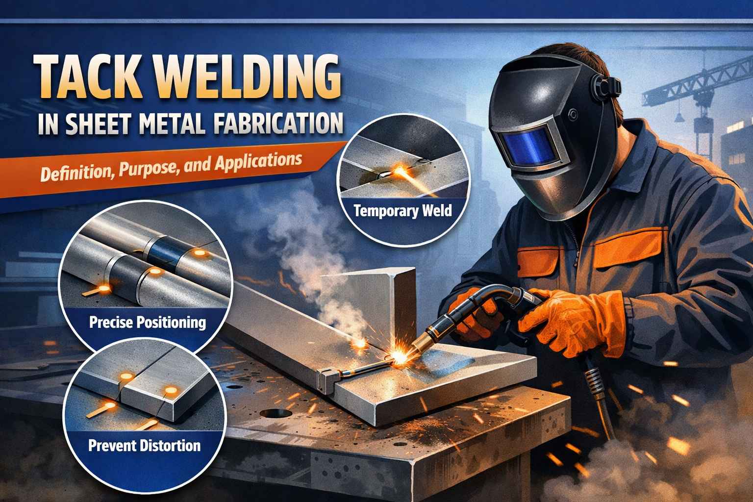
The joint design for robotic welding controls the gap and the access. Consistent gaps let the robot deposit a consistent weld; gaps that vary force the robot to either over-weld the tight sections or under-fill the open ones, and the weld quality follows the fit. Backing bars or backing gas support the root where full penetration is needed, and tacking holds the joint in place before the robot runs the production weld. The tacking pattern is part of the design: the tacks must hold the joint without creating gaps or distortion, and they must not interfere with the robot’s weld path. The joint design and the tacking plan are specified together, because the robot repeats what the tacks established.
The joint access also includes the seam tracking: a robot with seam tracking can follow a consistent joint, but it cannot compensate for a joint that varies wildly. The part should present a trackable seam.
Datum strategy and fixturing for repeatable parts
The fixture is the robot’s reference: it locates the part so the robot’s programmed path hits the joint every time. The part’s datum features — the edges, holes, and faces that the fixture contacts — must be consistent from part to part, and the drawing should define them so the fixture is built to the same reference the inspection uses. The fixture should locate the part against the datums and clamp it without distorting the joint, and the fixture maintenance should be part of the process control. A part that is designed with clear datums is a part the fixture can hold repeatably; one that locates by a feature that varies is a part the robot cannot weld consistently. The datum strategy is the bridge between the part design and the robotic cell.
The fixture should also be verified: a first part run through the cell confirms the path, and the fixture is checked on a schedule for the wear that shifts the location.
Volume threshold: when robotic welding pays
Robotic welding pays when the volume and the part consistency justify the cell investment. The threshold depends on the weld length, the cycle time, the labor cost, and the part family: a high-volume part with long welds can justify automation at a lower annual quantity than a low-volume part with short welds. The comparison should include the fixture cost, the programming, and the maintenance, and it should be made on the total cost per welded part. Robotic welding also pays through quality and repeatability, which reduce the rework that manual welding variability creates. The volume decision is an economic analysis with the part’s weld content and the forecast quantity as the inputs.
The threshold should also consider the part family: a cell that runs several similar parts can amortize the investment across them, and the design should keep the joint geometry consistent across the family.
Tolerancing welded subassemblies for automated lines
The tolerances on a robotic-welded subassembly should reflect the process and the fixture. The welded assembly does not hold machined tolerances; the critical dimensions are set by the fixture, the joint fit, and the weld sequence, and the drawing should allow realistic zones over the welded features. The precise interfaces should be machined after welding or located by the fixture, and the tolerance note should separate the welded structure from the machined features. The robot can repeat the process, but it cannot remove the variation from the parts and the fixture, so the tolerance plan should control the inputs that the robot depends on. A subassembly that is toleranced for the automated line is one the line can hold run after run.
The fabrication assembly service on this site covers the process; this page is the design discipline that makes the process work. When the access, the joints, the datums, and the tolerances are designed together, the robotic cell produces consistent welds — and the part design and the automation earn their investment together.
Qualifying the robotic weld process on the part
The robotic weld process is qualified on the actual part before the production run. The first article runs through the cell with the production fixture, the weld path is verified against the joint, and the resulting weld is inspected for the penetration, the profile, and the defects. The qualification results set the process parameters — the speed, the voltage, and the wire feed — and they confirm that the part design and the fixture produce a consistent joint. The qualification should also check the seam tracking and the tacking: a joint that the robot cannot track or that the tacks distort is a joint that needs the design fix. A robotic weld process that is qualified on the part is a process the production run can repeat; one that is set from a generic program carries the variation into every part.
The qualification should be repeated when the inputs change: a new material lot, a different wire, a repaired fixture, or a modified part can shift the weld result, and the process should be re-verified before the run. The weld inspection — the visual check, the dimensional check, and the destructive test where required — is part of the process control, and the records tie the weld quality to the part and the process. When the robotic weld process is qualified and controlled, the cell produces consistent welds run after run, and the design that was made for automation delivers the automation’s value — speed, quality, and repeatability.
The robotic weld design should also be reviewed with the part’s full production route, because the welding is one step in a sequence. The blank is cut, the parts are formed, the joint is fitted and tacked, and the robot welds — and each step sets the joint that the next step sees. A forming operation that distorts the joint, a cutting operation that leaves a variable edge, or a handling step that flexes the part all defeat the robot’s repeatability, and the design should control the variation at every step, not only at the weld. The process review should trace the part through its route and identify where the joint geometry is set and where it can drift, and the control plan should cover the upstream operations as well as the weld cell. The welding robot can repeat a consistent input, but it cannot correct an inconsistent part, and the design-for-robotic-weld discipline is really a design-for-consistency discipline across the whole route. When the production route and the weld cell are designed together, the automated weld is the reliable result of a controlled process — and the cell’s speed and quality are realized because the parts feed it consistently.
Keep the cell qualification records with the part so the weld process is reproducible when the part or the cell changes. The record is the reference for the re-qualification and the quality audit.
Confirm the weld inspection standard with the customer before the production run, because the acceptance criteria set the process and the records. The agreed standard — the visual class, the dimensional check, and the test frequency — is what makes the robotic weld a verified product rather than a visual guess.
If you are designing sheet-metal parts for robotic welding and want the access, the fixture, and the tolerance plan reviewed, the 6CProto sheet metal team can work from your weld content and volume to the design and the cell requirement.