

In a hypothetical housing trial, the lid fits and the finish looks correct, but the assembled device fails its EMI evaluation. The investigation finds that the finished contact surfaces and gasket gap differ from the intended configuration. For buyers, sheet metal manufacturing for device housings needs coordinated electrical interfaces, cosmetic criteria, and assembly acceptance before the finish is approved.
EMI seams and grounding points
Specify sheet metal manufacturing for device housings through the seam and aperture design, intended bonding paths, gasket interfaces, finish and masking, cosmetic zones, assembly sequence, and required validation. Separate dimensional acceptance, electrical continuity, shielding performance, and product safety. Confirm the finished configuration instead of assuming metal construction or a neat coating establishes every functional requirement.
Identify the contacts needed at lids, panels, connectors, and designated bonding points. Keep RF shielding and protective bonding requirements distinct in the design review. A connection that serves one purpose does not automatically establish the evidence required for the other.
Parker Chomerics’ shielding and gasketing discussion addresses the importance of interfaces and discontinuities. Use the device’s actual frequency and installation context to define the assessment. An enclosure material name or a single continuity reading cannot predict the assembled system’s EMC result.
Cosmetic vs functional faces
Mark visible faces, hidden faces, mating interfaces, and electrical contact regions separately. For cosmetic regions, define color, gloss or texture where required, viewing conditions, and acceptable defects. For functional regions, define the delivered surface and dimensional condition that supports the intended contact or fit.
Use the same drawing to prevent conflicts between those requirements. A coating can satisfy appearance while altering a gasket land, covering a contact region, or changing a close fit. Masking needs boundaries and an agreed edge condition, not merely a note to keep ground points clear.
PennEngineering’s finishing guidance discusses interactions between sheet-metal treatments and installed self-clinching hardware. Confirm the selected fastener, finish, and operation order. Do not assume that the hardware sequence can be changed without reviewing its installation and finished function.
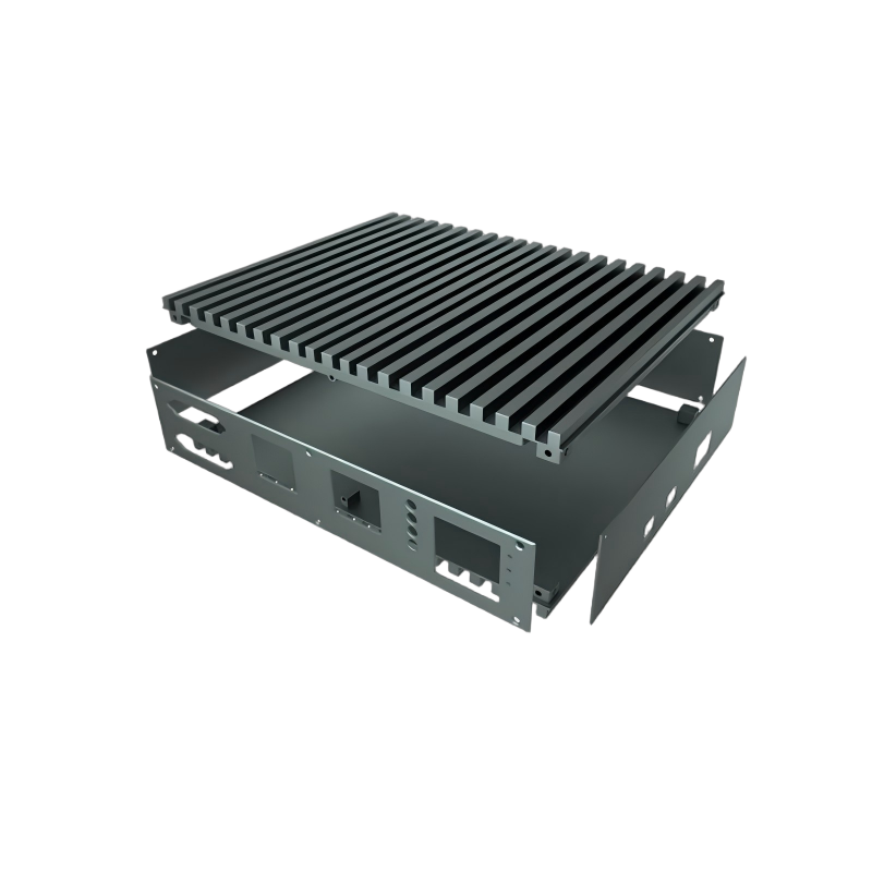
Table: finish options impact
Compare finishes by the delivered interface as well as the appearance. The table is a review framework, not a claim that a particular coating or treatment is included in every quotation. Confirm the material, product specification, preparation, and acceptance requirements for the actual order.
| Finish condition | Cosmetic question | Functional question | Evidence to agree |
|---|---|---|---|
| Paint or powder coating | Color, texture, visible coverage and defects | Which contacts, threads and mating regions need masking? | Representative finish and marked-interface inspection |
| Anodized aluminum | Approved appearance and consistency | How is the required electrical contact obtained? | Specified treatment and interface validation |
| Specified conductive treatment | Acceptable appearance and exposed areas | Does the delivered surface suit the selected contact pair? | Treatment documentation and required electrical checks |
| Uncoated contact region | Location and masking-edge acceptance | Corrosion, handling and repeated assembly behavior | Defined surface condition and relevant exposure review |
3M’s conductive gasket-tape guidance identifies compression, contact surface, resistance, shielding, and environment as selection factors. Evaluate the exact gasket and surface together rather than treating every conductive tape as an equivalent replacement.
Assembly sequence
Review assembly in the finished state: coating and masking, hardware installation, contact preparation where specified, gasket placement, closure, and inspection. Protect the approved surfaces during handling. A sample validated before finishing may not represent the order delivered afterward.
Use a gap calculation to expose an interface question early. For an illustrative 2.0 mm gasket closed to a 1.5 mm gap, compression is (2.0 − 1.5)/2.0 = 25%. If the actual assembled gap were 1.4–1.7 mm, the same arithmetic gives 30–15%. These are hypothetical dimensions, not an approved compression range for a gasket product.
Compare the tolerance stack with the selected manufacturer’s permitted conditions. Include panel form, hardware seating, closure support, and gasket variation where relevant. A nominal gap does not establish consistent pressure around the complete seam. Validate the representative closed assembly rather than only a short coupon.
FAQ
These questions address specification details that should be settled before sample approval.
Does a low DC resistance reading prove that an enclosure will pass EMI testing?
No. It addresses the measured connection under its stated conditions. Shielding performance also depends on frequency, seams, apertures, interfaces, and the installed configuration. Define the electrical checks and system EMC validation separately.
Can a cosmetic coating be applied everywhere without reviewing bonding?
No. Mark functional contact regions, masking boundaries, gasket interfaces, threads, and other surfaces whose delivered condition matters. Review the actual coating and contact arrangement. A uniform appearance does not establish the required electrical path or interface.
Related process selection notes
Allocate electrical safety and EMC responsibilities explicitly. IEC 62368-1 addresses product safety for equipment within its scope. It is not an enclosure shielding-performance certificate. The responsible product engineer should identify the applicable requirements and evidence for this device and its intended market.
ASME Y14.5 provides geometric communication rules for defining interfaces under the chosen drawing convention. Use suitable references for lid seating, connector alignment, and gasket lands. Keep electrical tests distinct from the dimensional report.
For a hybrid housing, the machined enclosure review may address local features or another construction route. Compare the complete seam, contact, finish, and inspection arrangement rather than assuming two nominally metal housings provide identical shielding or bonding behavior.

Internal links and next steps
Send the controlled drawings and model with quantity, material, cosmetic zones, finish and masking, gasket and hardware references, critical gaps, and the required records. State which tests are included in the procurement and which are performed by the product team.
Coordinate the sheet-metal fabrication review with the surface-finishing review. For a consumer-electronics device, include the installed connector, cable, and closure conditions that affect the interfaces.
Request a 6CProto device-housing review with the electrical interfaces and cosmetic acceptance defined. Approve the representative finished configuration and preserve it when material, finish, hardware, or gasket changes are proposed.
FAQ
These questions address specification details that should be settled before sample approval.
Does an EMI gasket automatically provide an environmental seal?
No. Confirm both functions for the exact product, geometry, compression, exposure, and installation. A conductive gasket may be selected for shielding without satisfying the required fluid or dust seal. Evaluate each acceptance requirement and the representative assembly.
Can the purchaser accept a housing from dimensions and photographs alone?
Only for the requirements those checks actually establish. Where electrical bonding, EMC, safety, sealing, or other functions matter, define the relevant evidence and responsibility separately. Preserve the tested finish, hardware, gasket, and assembly configuration so validation remains applicable.