

A hypothetical robot bracket meets its drawing dimensions but bends enough under payload to miss the intended task position. Buying a stronger alloy or tightening every tolerance can add cost without fixing the limiting compliance. Robotics machining parts need a cost review that connects material, section geometry, bearing interfaces, machining access, and assembled performance before weight is removed.
Stiffness vs mass targets
Specify robotics machining parts through load cases, stiffness and mass targets, joint interfaces, datums, bearing fits, cable motion, and final inspection. Compare complete manufacturing and validation costs. Material strength, nominal weight, or a tight bore alone cannot establish arm performance; evaluate the assembled load path and relevant operating conditions before approving geometry or process changes.
Separate machining cost from the cost of a useful assembly. The route includes stock, roughing, thin-wall finishing, fixtures, access, surface treatment, metrology, assembly, and validation. A heavily pocketed part can require more work and create a less stable interface even if its final mass is lower.
Universal Robots’ payload documentation distinguishes mass, center of gravity, and inertia in its configuration. This illustrates why mass alone is an incomplete system input. Use the actual robot and component requirements rather than transferring a payload assumption between platforms.
For a simplified static example, MIT’s cantilever review gives end deflection magnitude δ = FL³/(3EI). Assume F = 50 N, L = 0.20 m, E = 70 × 10⁹ Pa, and I = 1.0 × 10⁻⁸ m⁴. The calculated deflection is about 0.190 mm. All inputs are hypothetical, not specified material data or a measured robot result.
Within that idealized beam model, doubling I halves bending deflection. This explains why section geometry deserves attention alongside material selection. It does not include joint compliance, dynamics, backlash, or control effects and cannot establish positioning accuracy.
Bearing bores and stacks
Map the bearing arrangement, shoulders, spacers, fastener seats, and axis relationships before assigning local tolerances. Define which features locate the axis and which provide clearance. Review the final coating state and the effect of assembly, mounting force, and temperature on the required fit.
SKF’s installation and maintenance guide identifies loading, internal clearance, temperature, housing and shaft design, and other factors in fit selection. It is a reference guide, not a substitute for application-specific bearing design. Obtain guidance for the actual bearing and duty instead of adopting a universal bore fit.
For an illustrative one-dimensional stack, two independent dimensions specified as ±0.02 mm each can contribute ±0.04 mm in a simple worst-case sum when both affect the result in the same direction. Those assumed values are not recommended tolerances. Establish the actual chain, signs, datum relationships, assembly state, and acceptance method before assigning the limits.
ASME’s Y14.5 overview identifies a language for geometric requirements. Use the drawing’s selected convention consistently. Do not expect a size tolerance alone to control every form, orientation, or location requirement of a bearing interface.
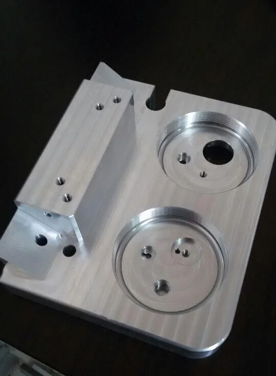
Table: material candidates
Use actual grade and condition data for the decision. The table lists candidate roles and questions, not approved materials for every robot or a ranking based on generic family properties.
| Candidate | Potential role | Question before purchase | Cost or evidence consequence |
|---|---|---|---|
| Selected aluminum alloy | Arm section or machined bracket | Does geometry meet stiffness, fatigue and interface needs? | Stock, pockets, fixtures, finish and validation |
| Selected steel grade | Shaft, insert or demanding contact | What material condition, treatment and fit apply? | Mass, processing, inspection and assembly |
| Suitable engineering polymer | Cover or nonstructural interface | What load, heat, wear and environmental limits apply? | Grade-specific evidence and dimensional control |
| Approved hybrid assembly | Light body with separate bearing or wear interfaces | How are parts located, retained and replaced? | Additional joints, hardware and assembly checks |
Changing an alloy or adding a separate insert may alter more than the machining line item. Review thermal relationships, corrosion interfaces, retention, maintenance, and the relevant functional tests. Confirm the bill of materials and final assembly responsibilities in the quotation.
Cable routing and covers
Route cables through the full motion range, not only the home position. Identify bend, torsion, clearance, strain relief, connectors, and service access using the selected cable supplier’s requirements. Avoid imposing a universal bend-radius factor on every cable construction or installation.
igus’ robotic cable information distinguishes cables intended for robotic torsion and dynamic motion. It supports selecting for the actual movement rather than treating a static cable passage as sufficient. Confirm the particular cable and its applicable installation conditions.
Review passage edges, openings, cover screws, and protrusions alongside moving geometry. Include the effect of an opening on the load-bearing section. Specify deburring, edge condition, protected contacts, and cover fit where relevant, then check the assembled routing and maintenance access.
FAQ
These questions address specification details that should be settled before sample approval.
Does a higher-strength alloy automatically make a robot arm stiffer?
No. Strength and stiffness are different properties. Geometry, elastic modulus, joints, bearings, load path, and operating conditions affect deflection. Assess the complete structure and relevant material condition rather than selecting an alloy from a strength number alone.
Can a tight bore tolerance guarantee the joint will run correctly?
No. Bearing selection, fit, form, alignment, shoulders, mounting, thermal behavior, and the surrounding stack also matter. Use guidance for the actual bearing and application, and define inspection in the required final condition. One diameter does not describe the entire joint.
Related process selection notes
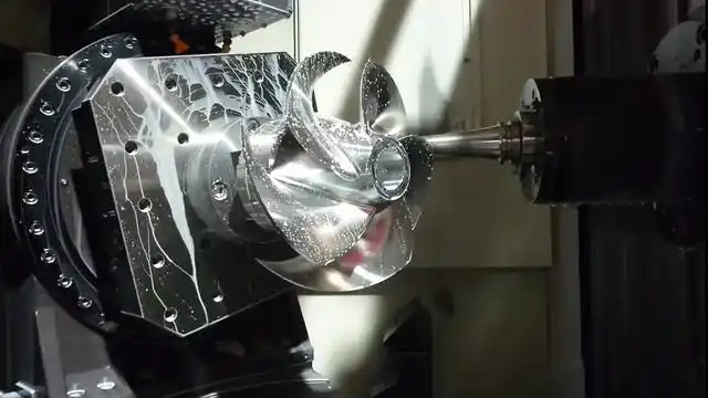
Compare routes on the same design baseline. A five-axis approach may change access and repositioning, while a simpler setup can be economical for different geometry. Ask which operations, fixtures, and inspections the proposal requires rather than assuming more axes reduce total cost.
Keep structural and dimensional evidence distinct. Inspect critical final features, then validate the assembled behavior relevant to the operating requirement. Record loads, mounting, temperature, measurement locations, and other conditions needed to interpret a trial. A passing unloaded dimensional report does not close an unresolved loaded-deflection question.
Use the results to target the next revision. Improve the limiting section or interface and reassess affected requirements before adding tighter tolerances everywhere. Preserve the approved configuration for repeated parts and maintenance.
Internal links and next steps
Send the model, drawing, quantity, material condition, load cases, stiffness and mass targets, bearing details, cable route, finish, and acceptance plan. Review the application through robotics components and the manufacturing route through CNC machining. Compare aluminum options and five-axis access where relevant.
Request a robotics-part quote with the load path and final-interface requirements defined. Compare the complete accepted component and assembly evidence.
FAQ
These questions address specification details that should be settled before sample approval.
Can the example beam calculation predict robot positioning accuracy?
No. It is a simplified static bending illustration with explicitly assumed inputs. A real robot includes joint compliance, transmission behavior, control, thermal effects, load variation, and dynamics. Use an appropriate system model and representative validation for the actual requirement.
Can cable passages be added after the structural design is complete?
They need an integrated review. Passages and access openings can affect stiffness, machining, contact edges, cover attachment, and cable motion. Verify the routing and service access across the intended motion range before releasing the component design.