

Every component in a mixed-process assembly can meet its drawing and still leave the assembly outside its functional limit. A machined base, formed bracket, and molded cover do not necessarily contribute variation in the same way. Buyers comparing suppliers need an assembly objective and an agreed analysis model before treating a tighter quoted tolerance as the solution.
Why mixed processes break naive stacks
Evaluate tolerance stacks across mixed processes from the assembly function, actual locating scheme, final surface states, and relevant dimensional and geometric variation. Define the model before selecting worst-case or statistical methods. Align supplier requirements and inspection conditions, then validate representative assemblies; a collection of acceptable local dimensions cannot by itself establish fit or functional performance.
Start with what must work: clearance, alignment, gasket compression, travel, visual flushness, or another measurable objective. Identify the contact and locating sequence that produces it. A list of nominal dimensions is not yet a model of how the parts are assembled.
Consider an explicitly hypothetical one-dimensional chain C = H − A − B. Let H = 30.00 ±0.05 mm, A = 10.00 ±0.10 mm, and B = 19.50 ±0.15 mm. Nominal clearance is 0.50 mm. Under independent dimensional limits in this linear chain, the minimum is 29.95 − 10.10 − 19.65 = 0.20 mm and the maximum is 30.05 − 9.90 − 19.35 = 0.80 mm.
These assumed values illustrate worst-case arithmetic, not recommended tolerances or actual supplier capability. The model omits angle, form, assembly shift, deformation, temperature, and finishing unless they are represented in its inputs. Decide whether those omissions are acceptable for the real interface.
Sigmetrix’s analysis discussion distinguishes limit-based and statistical questions. Use the method that answers the requirement with supported assumptions. Do not turn drawing limits into measured probability distributions by assumption.
Datum schemes across suppliers
Align the physical reference across the base, bracket, cover, and their inspections. Identify which surfaces locate, which are allowed to float, and where fastener clearance or contact changes the position. Define the intended assembly restraint and sequence where they affect the result.
ASME’s Y14.5 overview describes a language for geometric requirements. Apply the chosen convention to the actual datum features and relationships. Matching datum letters on separate drawings do not by themselves create an identical assembly or inspection reference.
For a formed part, review bends and the resulting functional geometry, not only flat-pattern dimensions. Autodesk’s sheet-metal rules reference identifies thickness, radius, relief, and unfolding inputs. Confirm the actual fabrication route and final requirements rather than expecting an unreviewed CAD rule to establish the delivered shape.
Document how a molded part’s condition, a finished machined face, or assembly loading affects the reference. Ask suppliers to identify inspection fixtures and assumptions that differ from the actual assembly. Resolve those differences before comparing results.
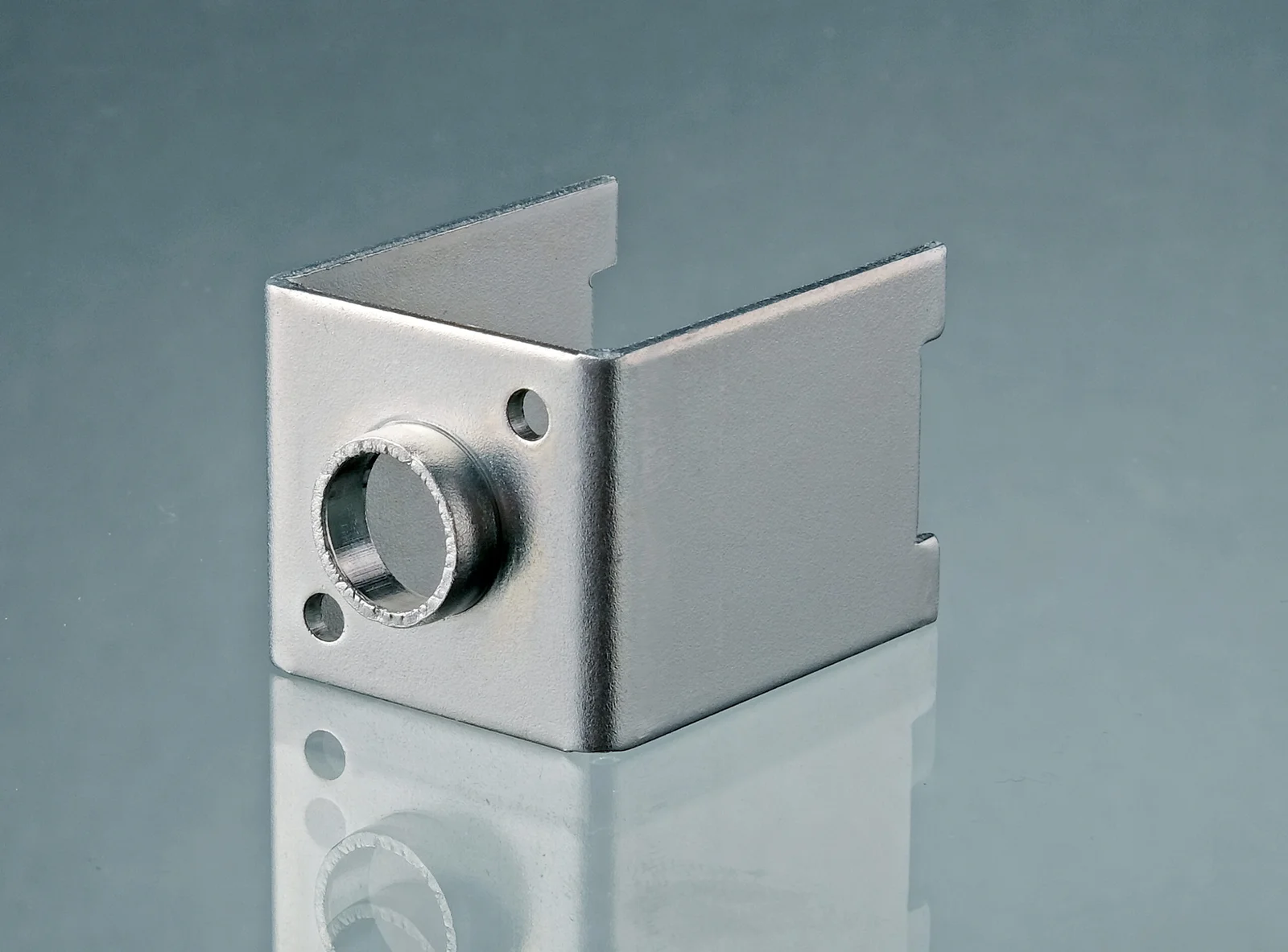
Table: methods overview
Choose the method after defining the model and available evidence. The table summarizes questions to ask, not a rule that one process or volume always requires a particular analysis.
| Method | Question addressed | Inputs to establish | Important boundary |
|---|---|---|---|
| Worst-case limit analysis | What extremes do the modeled limits permit? | Correct chain, signs, bounds and geometric effects | Does not estimate occurrence probability |
| Simple RSS model | What combined variation follows under its assumptions? | Appropriate variation scale, relationships and dependence | Not a guaranteed assembly envelope |
| Broader statistical model | How do supported distributions affect the objective? | Process data, correlations and suitable model | Predictions depend on input quality and validity |
| Representative assembly evaluation | What happens in the tested configuration? | Traceable parts, conditions and acceptance | Sample results do not cover every untested combination |
Autodesk’s tolerance-analysis reference distinguishes worst-case, RSS, and statistical treatments, including handling of shifts. Check the software’s conventions and model scope. A green result cannot compensate for an omitted contributor or a false process assumption.
For procurement, request the acceptance objective and relevant analysis assumptions with any proposed tolerance change. Separate a drawing change from a prediction of process performance. Avoid comparing two supplier proposals that use different final states or different meanings of statistical capability.
Practical mitigations
Target the controlling contributors rather than tightening every number. Options can include a shorter locating chain, a common machining reference, a dedicated locator, adjustment, a controlled spacer, revised geometry, or a different process for a critical interface. Evaluate their cost and functional consequences together.
If adjustment is selected, specify its range, setting method, locking, and verification. If selective assembly is proposed, define identification and replacement requirements. Neither should become an undocumented workaround that future production or maintenance cannot reproduce.
NIST’s dimensional-metrology FAQ discusses temperature and measurement considerations. Agree the relevant reference condition and material state when comparing dimensions from different sources. A warm-part reading and a later assembly measurement may not describe the same condition.
Keep the final finish and functional surfaces in the chain. Review coating growth, masking, surface contact, and any post-processing that affects the locating features. Preserve the approved configuration when validating the mitigation.
FAQ
These questions address specification details that should be settled before sample approval.
Can every supplied part pass inspection while the assembly still fails?
Yes. Local requirements may permit a combination that violates the assembly objective, or the inspection and assembly may use different references or conditions. Review the complete functional chain and the assumptions behind each part requirement. Passing individual drawings does not automatically establish assembled fit.
Can RSS replace worst-case analysis whenever the sum looks too large?
No. Statistical analysis needs appropriate distributions, process evidence, dependence treatment, and a suitable assembly model. Document the assumptions and required confidence or acceptance basis. A smaller computed range is not justification for using an unsupported statistical model.
Related process selection notes
Build an interface matrix linking the assembly objective to each part feature, supplier requirement, inspection, and final condition. Identify the owner of the complete stack and the evidence needed to close it. A component provider can respond to its own scope while the integrator remains responsible for reconciling the assembly.
Compare targeted revisions against the complete accepted-part route. A tighter feature may require different tooling, setup, inspection, or secondary work. A redesigned locator can sometimes change the whole chain. Obtain a controlled proposal and engineering disposition before altering a purchase order.
Record trial results with part revisions and conditions. If the design, process, finish, or material changes, assess the affected contributors and repeat the relevant work. Treat the analysis as a model that needs evidence, not a permanent approval of all future assemblies.
Internal links and next steps
Send the assembly model, controlled drawings, function and limits, locating scheme, material and finish conditions, supplier split, and available variation data. Review the tolerance requirements alongside CNC, sheet fabrication, and molding where relevant.
Request a mixed-process quote with the assembly objective and critical-interface matrix attached. Confirm each component’s scope and the final verification plan before release.
FAQ
These questions address specification details that should be settled before sample approval.
Does a common datum letter create a common physical reference across suppliers?
No. Each drawing must identify the actual datum features and how the requirements relate to the assembly. Reconcile locating, restraint, finish, and measurement conditions. Reusing a label does not establish that different parts or inspections use the same functional reference.
Should every component tolerance be tightened equally?
No. Determine which contributors control the assembly objective and which changes preserve function at practical cost. Options include datum changes, locating features, adjustment, process changes, or targeted tolerances. Have the responsible engineer approve the revised requirements and verify the resulting assembly.