

Explore Injection Molding Materials, Defects & Validation
A soft grip can remain attached during a straight pull yet peel away when a user catches its exposed edge. Adding holes through the rigid substrate may improve retention, but it also changes flow, venting, substrate strength and tooling access. The useful design question is how the second material transfers the actual service load into the first.
Overmolding mechanical interlock design should establish a geometric load path independently of any assumed chemical adhesion. Adhesion may contribute when the selected material pair and process support it, but a claim that two materials bond is not a substitute for verifying the complete component.
This guide concentrates on holes, ribs, wraparound features and undercuts that retain the second material. It treats straight pull, edge peel and environmental exposure as distinct validation questions. Retention alone does not establish a fluid seal or eliminate movement at every part of the interface.
Discuss the load directions with the overmolding review. Include the substrate model and the finished assembly, rather than only the visible soft surface. The sections below help connect the required retention to geometry that can be molded, released and inspected consistently.
What does an overmolding mechanical interlock actually retain?
Geometry carries load without proving chemical adhesion.
A filled hole, wraparound edge or undercut transfers force through bearing, shear or deformation of the second material; its retention depends on geometry and the actual loading direction.
Draw the load path through both materials. A soft plug through a hole may resist direct separation but still stretch or tear when peeled from one side. The substrate around that hole also needs enough remaining section to transfer the load without cracking or deforming.
Teknor Apex's overmolding guide distinguishes material matching from the use of mechanical interlocks to reinforce attachment. Select the exact substrate and overmold grades before deciding whether adhesion contributes to the intended design.
State the design assumption explicitly. A mechanically retained grip may tolerate local interface separation while remaining attached; a sealing interface may not. Do not describe successful retention as evidence of a continuous bond or a leak-tight boundary. Those are separate functional requirements with different failure criteria and potentially different test methods.
Holes, ribs and undercut access
Select retention geometry by the load direction and the molding route. Through-holes can connect material on opposing faces; a wraparound edge can capture a substrate; undercuts can resist withdrawal along a chosen axis. Each creates a different path for flow and tool release.
Avient's overmolding part-design guidance illustrates mechanical interlocks and warns against deep, unventable features. Apply its principles to the selected grade and geometry without converting example dimensions into universal design rules.
Check how the tool forms and releases every interlock. A retaining shape in the product can also be an undercut in the mold. Side actions, removable inserts or elastic release may change the tooling concept and the stresses imposed on the soft feature during ejection.
Review the substrate’s remaining ligament, corner transitions and support in the second-shot tool. More holes do not automatically improve the assembly if they weaken the rigid load path. Keep sharp transitions away from highly loaded soft necks where tear initiation could dominate the result.
Flow around the substrate
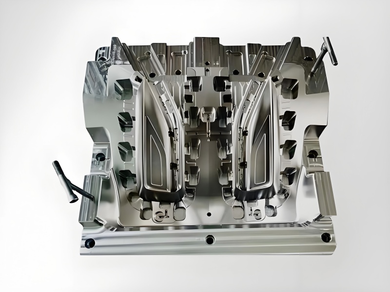
The second material must reach and fill the retaining features before they can contribute to attachment. A surface that appears fully covered can hide an incompletely filled hole or a weak meeting region beneath the substrate. Review the fill path through the actual retention geometry.
Identify where flow splits, where air must leave and where fronts meet after passing around an obstruction. Gate placement influences these regions and may affect the load path. A mechanical interlock positioned far from effective packing can be less repeatable than its nominal CAD shape suggests.
The Avient GLS overmolding guide discusses flow, shutoffs and interlocks as connected design considerations. Use the material supplier’s grade-specific processing information for the detailed trial; avoid adopting a guide’s example pressures or wall dimensions as general parameters.
Support the substrate against second-shot forces while keeping the required flow and vent paths open. Inspect the candidate tool layout for material leakage onto contact faces. A retained overmold that flashes across an assembly interface can fail the product requirement despite excellent attachment in a pull test.
Validate pull, peel and environmental loading
Test the ways the product can actually load the interface. A normal pull distributes force differently from edge peel, torsion or repeated rubbing. Select fixtures that reproduce the relevant direction and contact region rather than testing whichever grip arrangement is easiest to mount.
Define the required displacement or load, test rate, temperature and conditioning state. Where the application exposes the part to fluids or temperature changes, use the specified exposure sequence before the relevant mechanical check. Retain an unconditioned comparison to distinguish baseline geometry from exposure-related changes.
Record whether failure occurs by interfacial separation, soft-material tearing, plug pull-through or substrate fracture. These observations identify different design limitations even when peak loads are similar. A force value without a failure description can lead to the wrong corrective action.
Keep local edge movement separate from total separation. A grip may remain attached while developing an objectionable lifted edge. Define that visual or dimensional boundary if it affects use, cleanliness or appearance. Passing the ultimate separation load alone does not close those requirements.
A retention specification for the two-material component
Specify the features that establish retention and the observations that define failure. The drawing should identify hole or undercut geometry in the substrate, the second-material envelope and the final state used for inspection. A generic instruction to provide a strong bond leaves the acceptance route undefined.
The following framework separates geometry, appearance and performance. Project-specific limits belong in the released requirement and test procedure.
| Feature or test | Controlled condition | Failure to distinguish |
|---|---|---|
| Retention opening | Size, position and remaining ligament | Substrate weakness |
| Filled interlock | Complete defined material envelope | Short fill or internal discontinuity |
| Exposed edge | Lift and residual flash | Peel initiation or interference |
| Mechanical test | Load direction and conditioning | Tear, pull-through or separation |
The insert-molding route may affect substrate handling and location. Record how the substrate is identified and seated before the second shot, because mislocation changes both the visible boundary and the material remaining around an interlock. Inspection should verify the final feature, not merely the existence of the opening before molding.
Separating interlock geometry from material and process changes
Use a trial matrix that separates geometry, material and process changes. Establish the substrate revision, exact material grades, color system, preparation method, second-shot tool and sample identities. Keep any release agent or cleaning operation traceable because interface conditions can influence the observed result.
Avient's overmolding processing guidance identifies moisture, substrate preparation, colorant compatibility and process conditions among adhesion factors. Even a primarily mechanical design should control those variables so their effect is not confused with the interlock geometry.
Inspect initial filling before committing every sample to destructive testing. Allocate identified parts to sectioning or another suitable inspection when hidden retention features cannot be checked externally. Reserve other parts for the complete functional tests so sample preparation does not alter the intended load path.
Compare candidate geometries under representative molding conditions. A hand-filled demonstration or bonded laboratory coupon can support a limited question, but it does not reproduce the second-shot flow and ejection history. Record what each specimen represents so a promising experiment does not become an unsupported production release.
Checking hidden fill, edge lift and substrate distortion
Check the rigid substrate after the second shot, especially around support points and thin regions. Differential shrinkage and process forces can distort the finished assembly even if the uncoated substrate passed its original inspection. Retention geometry and final fit therefore need coordinated acceptance.
Inspect soft-material coverage, flash at shutoffs, exposed edge condition and fill within the defined retention envelope. A cosmetic texture can make a defect less visible without removing it. Where a contact or sealing face must remain clear, verify that face independently of the grip’s appearance.
Avient's overmolding troubleshooting guidance distinguishes short shots, substrate support problems, warpage and poor adhesion. Those categories help interpret the result rather than treating every attachment failure as a material-compatibility issue.
Test the complete assembled product where adjacent parts constrain the overmold. A mating shell can compress an edge, alter peel initiation or restrain deformation. Conversely, it can conceal a defect during inspection. Define whether acceptance applies before assembly, after assembly or at both stages, and preserve the observations needed to explain any difference.
Releasing the interlock with its material pair and tests
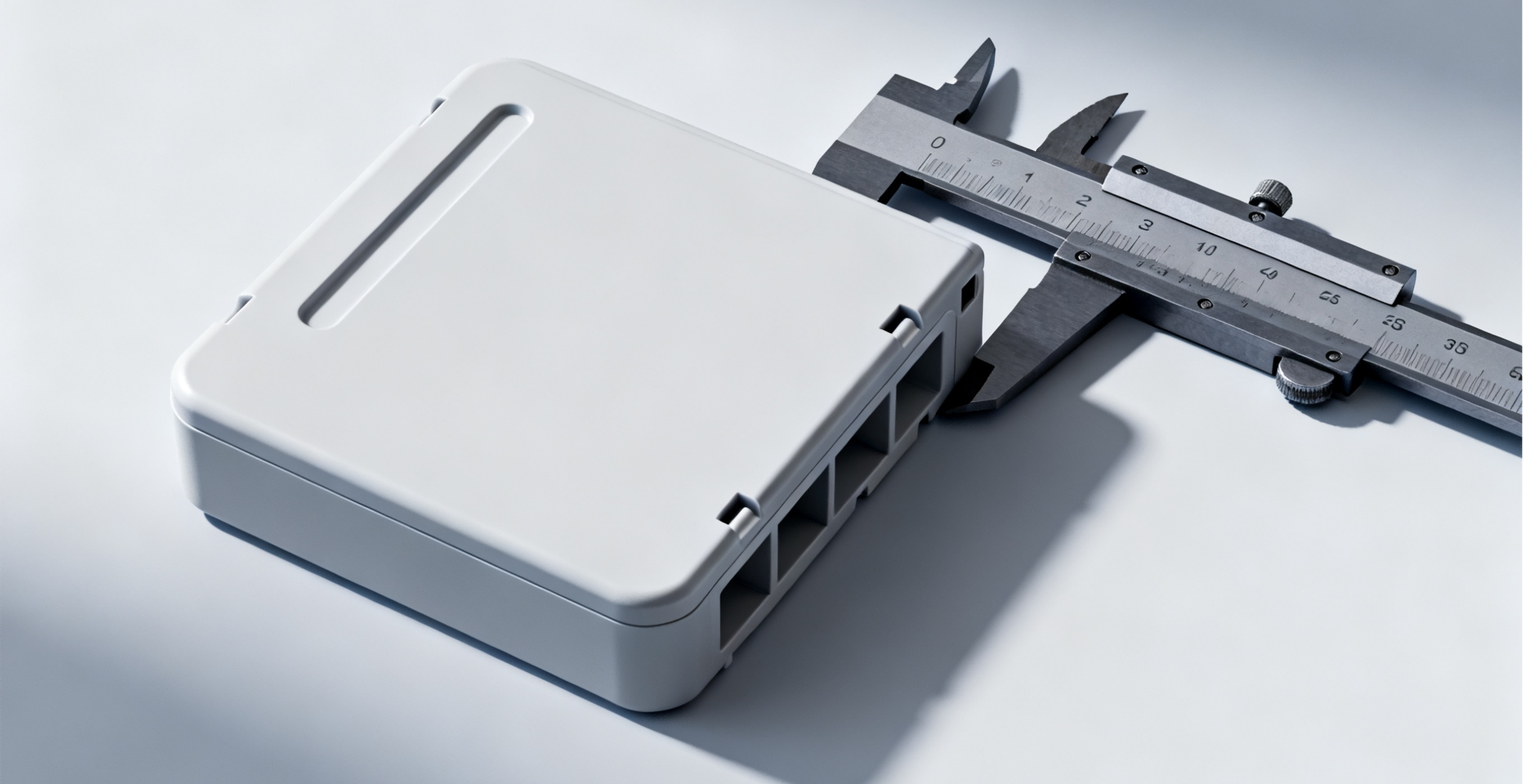
Release the component when the selected geometry can be filled and demolded consistently, the substrate remains acceptable, and the required tests pass in the specified states. Retain the approved tool and material configurations alongside the test procedure and representative evidence.
Resolve open assumptions about adhesion, hidden fill, edge movement and environmental exposure. A mechanically locked prototype does not establish that a production material substitution will behave equivalently. Likewise, an apparent bond on a freshly molded sample does not prove the interlock will survive the application’s loading.
Tie later changes to the affected evidence. A new color carrier may influence interface behavior; a relocated gate can alter a hidden meeting region; a revised hole can change substrate strength. State which changes require renewed testing rather than relying on the original approval by default.
Keep the manufacturing discussion focused on the finished two-material component. The injection-molding service context establishes the process route, while the project drawing, material pair and qualification results establish what is acceptable. A general process description cannot certify a particular interlock or sealing function.
FAQ
Can a mechanical interlock make an incompatible pair leak-tight?
It can prevent gross separation without sealing the interface. Fluid can travel along a locally detached boundary even when plugs or wraparound features keep the materials together. If sealing matters, define the seal geometry, fluid, pressure, temperature and test sequence separately. Consider whether the design needs a compatible material pair, controlled compression or another sealing mechanism. Retention test results alone should not be used to approve a leak requirement that was never evaluated.
Is a textured substrate equivalent to a through-hole interlock?
Texture may influence attachment and local mechanical engagement, but it does not create the same macroscopic load path as a filled opening or captured edge. Its effectiveness depends on the actual texture, material pair and molding conditions. Describe the surface specification and test it under the relevant load rather than treating any roughness as a defined interlock. Keep the distinction visible in the drawing and qualification record, especially when material adhesion is uncertain.
Should the design allow the overmold to be removed for recycling?
If disassembly is a product requirement, include it when selecting retention geometry. A permanent interlock can make separation difficult or destructive, while a removable arrangement may need different service-load protection. Define the intended removal method and the state of both materials after removal. Test service retention and deliberate disassembly as separate functions. Do not assume that a joint designed to resist peeling will also separate cleanly without an explicit release feature or approved process.
Conclusion
An effective interlock has a clear load path, a fillable and releasable shape, and tests that address pull, peel and the specified environment. Its success should be demonstrated as a complete two-material component. Keep adhesion, retention and sealing as separate requirements so each conclusion rests on the evidence that actually supports it.
Send 6CProto the substrate and finished-part models for a quotation, with both material grades, load directions, edge-lift limits and required conditioning. These inputs make the tooling and retention review specific to the product’s intended use.
{“@context”: “https://schema.org”, “@type”: “FAQPage”, “mainEntity”: [{“@type”: “Question”, “name”: “Can a mechanical interlock make an incompatible pair leak-tight?”, “acceptedAnswer”: {“@type”: “Answer”, “text”: “It can prevent gross separation without sealing the interface. Fluid can travel along a locally detached boundary even when plugs or wraparound features keep the materials together. If sealing matters, define the seal geometry, fluid, pressure, temperature and test sequence separately. Consider whether the design needs a compatible material pair, controlled compression or another sealing mechanism. Retention test results alone should not be used to approve a leak requirement that was never evaluated.”}}, {“@type”: “Question”, “name”: “Is a textured substrate equivalent to a through-hole interlock?”, “acceptedAnswer”: {“@type”: “Answer”, “text”: “Texture may influence attachment and local mechanical engagement, but it does not create the same macroscopic load path as a filled opening or captured edge. Its effectiveness depends on the actual texture, material pair and molding conditions. Describe the surface specification and test it under the relevant load rather than treating any roughness as a defined interlock. Keep the distinction visible in the drawing and qualification record, especially when material adhesion is uncertain.”}}, {“@type”: “Question”, “name”: “Should the design allow the overmold to be removed for recycling?”, “acceptedAnswer”: {“@type”: “Answer”, “text”: “If disassembly is a product requirement, include it when selecting retention geometry. A permanent interlock can make separation difficult or destructive, while a removable arrangement may need different service-load protection. Define the intended removal method and the state of both materials after removal. Test service retention and deliberate disassembly as separate functions. Do not assume that a joint designed to resist peeling will also separate cleanly without an explicit release feature or approved process.”}}]}