

In a hypothetical inspection trial, a printed locating nest passes its first fit check but shifts after repeated warm workpieces are loaded. Increasing infill may leave the real problem unresolved. FDM jigs and fixtures need a defined load path, thermal exposure, locating strategy, and maintenance plan before filament selection or a low print-cost estimate becomes meaningful.
Loads and heat on shop fixtures
Design FDM jigs and fixtures around the locating function, loads, temperature and duration, chemical contact, wear, printed structure, and required inspection. Select the actual filament and validate the representative tool. Include inserts, contact elements, finishing, and maintenance in the cost comparison rather than treating filament consumption or infill percentage as the complete engineering specification.
Separate workpiece weight from clamp force, handling impact, and any operation that loads the fixture. Identify which surfaces locate, which support, and which merely provide clearance. A printed body can be suitable for one function while needing another material at a highly loaded or wearing interface.
Stratasys’ jig-and-fixture resources describe applications for holding, positioning, and guiding parts. For the proposed tool, define the actual operation and acceptance requirements. An example of successful printed tooling elsewhere does not establish the capability of a different material and geometry.
Infill and orientation
Follow the load through the geometry and layer arrangement. Review perimeters, top and bottom layers, local solid regions, and the bond between deposited paths. An infill setting cannot describe all those features or compensate for an unsuitable orientation.
Prusa’s infill guidance distinguishes the contribution of perimeters and interior fill. Use that as a reason to assess the full sliced structure. Do not turn a general infill recommendation into a universal fixture-strength rule.
Ask how critical bores, thin walls, and insert bosses are constructed. Confirm whether changing orientation for strength affects support marks, flatness, or access. Include the agreed settings and material state in the sample record where they matter to repeatability. A visually identical print can have a different internal structure.
Inserts and wear pads
Review metal inserts, sleeves, wear pads, and replaceable contact pieces as part of the original design. They can separate the printed body’s positioning or support role from a locally demanding interface, but each introduces attachment and inspection requirements.
SPIROL’s printed-assembly insert study relates performance to the insert and host print conditions. Apply suitable supplier guidance to the actual hole, surrounding structure, and installation route. Its test results are not a universal pull-out or torque rating for every printed fixture.
Specify whether wear parts are supplied, installed, and inspected in the quotation. Identify replacement access and the reference surfaces that must remain stable after maintenance. A cheap printed body can create an expensive tool if every worn contact requires rebuilding and requalifying the entire assembly.
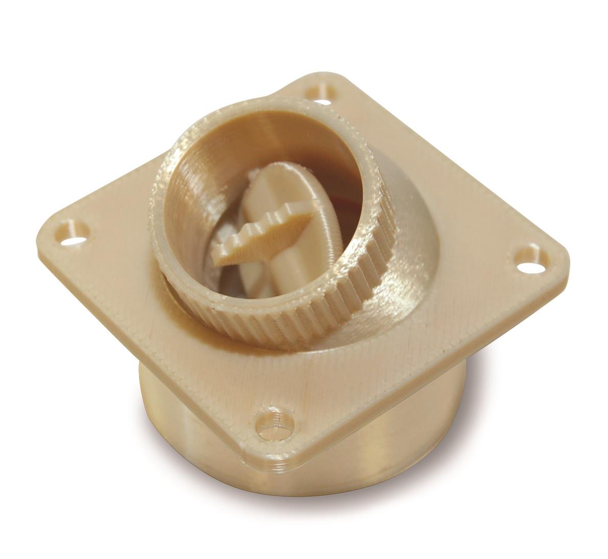
Table: filament choices
Shortlist filaments against the actual duty and printer route. The table organizes questions rather than certifying every family for a shop-floor application. Confirm the proposed product, printed properties, processing history, and required environment before approval.
| Candidate | Potential reason to review | Important question | Evidence needed |
|---|---|---|---|
| PETG grade | General fixture or handling component | Does loaded temperature, creep and chemical exposure fit? | Printed-grade data and representative duty trial |
| PC or PC blend | A more demanding thermal or mechanical requirement | Can the actual formulation be printed and stabilized appropriately? | Relevant print-state data and geometry validation |
| Nylon grade | Toughness or selected contact behavior | What conditioning and fit requirements apply? | Grade-specific dimensional and functional checks |
| Filled engineering filament | Specified stiffness or another targeted property | What happens to directionality, interfaces and wear? | Applicable data and final-component assessment |
UltiMaker’s PETG data reports printed specimens and identified directions. Read those conditions rather than selecting a convenient strength number. Prusa’s PC guidance distinguishes formulations and printability, reinforcing the need for a specific product rather than a generic PC label.
FAQ
These questions address specification details that should be settled before sample approval.
Does a higher infill percentage guarantee a stronger fixture?
No. Perimeters, local wall structure, orientation, bonding, material, geometry, and the load path also matter. Review the complete printed structure and validate the required function. A percentage by itself is not a strength specification.
Can a filament heat rating establish the loaded fixture temperature limit?
No. The actual grade, print state, stress, duration, geometry, and required accuracy must be assessed. A brief material test and sustained service loading are different conditions. Validate the representative fixture under the conditions relevant to its operation.
Related process selection notes
Compare the complete tool cost through design, printing, support removal, interface finishing, bought-in hardware, assembly, inspection, and maintenance. A longer print may be acceptable if it reduces a separate operation; a lighter print may be poor value if it requires frequent replacement or adjustment.
Use a sample to investigate the limiting feature. Measure locating relationships, check installation and removal, and assess behavior under representative load, temperature, and contact conditions. Do not assume a passing room-temperature first fit validates repeated warm operation.
If a printed body cannot provide the required stability or interface, consider an approved hybrid or another route. The objective is a useful and verifiable fixture, not maximizing the fraction of printed material. Confirm who approves the tool for its actual manufacturing or inspection operation.
Internal links and next steps
Provide the model, controlled drawing, quantity, workpiece interfaces, load and exposure details, service cycle information, critical dimensions, and required records. Include inserts, pads, hardware, and any customer-supplied components in the bill of materials.
Use the FDM review to confirm the proposed filament and print route, then compare options through the 3D-printing discussion. Align the first build with the prototype validation objective and define the checks needed before operational use.
Request a 6CProto fixture quote with the load path, thermal duty, and contact elements defined. Compare the complete delivered tool and its acceptance work, then record the approved configuration for repeat orders and maintenance.
FAQ
These questions address specification details that should be settled before sample approval.
Are metal inserts automatically reliable in any printed hole?
No. Insert type, hole geometry, surrounding printed structure, installation method, and loading affect performance. Follow applicable supplier guidance and verify the actual joint. Do not transfer a test result from another polymer or print structure without review.
Should every contact point be printed in the body material?
Not necessarily. Replaceable wear pads, bushings, or other approved elements may better serve repeated contact, heat, or load. Evaluate their attachment, location, and effect on the workpiece. Compare the complete fixture and maintenance route rather than minimizing purchased components alone.