

A profile drawing is a strange document by conventional drafting standards: it shows one section and implies an infinite length, and almost every dimension on it is a decision about material flow rather than about assembly.
What an extruded profile actually is
The part is defined entirely by its cross-section. Everything the profile does — carrying load, holding a seal, hiding a cable, providing a mounting flange — is a property of that section, repeated along the length. The consequence is that a change of section is a change of die, while a change of length is only a cutting operation. That distinction determines what is worth designing carefully and what is not.
| Section feature | Function it serves | What it costs to specify |
|---|---|---|
| Outer wall and flanges | Stiffness, mounting surface | Wall thickness affects cooling and tolerance |
| Internal webs | Stiffness without added weight | Web thickness should track the outer wall |
| Chambers | Cable routing, thermal separation | Requires mandrels and reduces achievable tolerance |
| Grooves | Seal or strip retention | Dimensional control where the component fits |
| Surface finish | Appearance and grip | Die finish is free; applied texture is a second operation |
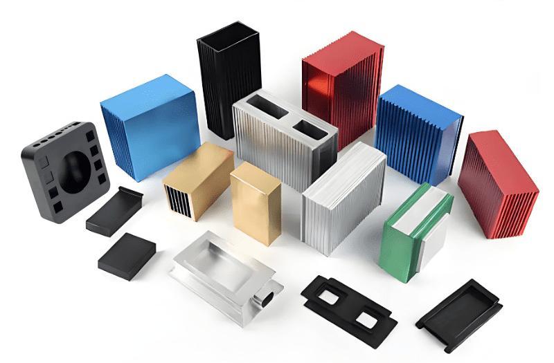
The different types of plastic extrusion
Four variants cover most work. Solid profile extrusion produces a section with no internal voids, which is the simplest to run and to hold to tolerance. Hollow or multi-chamber extrusion uses internal mandrels to form closed cavities and is common for window frames, ducts and cable ducts. Co-extrusion runs two or more materials through the same die so a rigid body can carry a flexible sealing lip or a differently coloured surface. And post-extrusion operations, such as adding a laminated film or a flocked surface, turn the profile into a composite component.
The distinctions matter for cost rather than terminology. Each additional material stream, each internal chamber and each secondary process adds a variable the die designer must account for, and each one reduces the tolerance the finished profile can reliably hold. A section that looks modest on paper can be demanding in the die if it combines hollow chambers with a soft sealing lip.
How wall thickness should be specified
As uniformly as function allows, with key features called out.
Material cools as it leaves the die, and thin sections cool faster than thick ones. Where a profile mixes thick and thin walls, the thick region is still shrinking while the thin one has set, which bends the profile or warps the section. Keeping walls reasonably uniform is the single most effective design decision, and it is what allows the process to hold the dimensions that matter.
The practical specification is a nominal wall thickness with a general tolerance, plus individual control on the features that mate with something else: a groove that holds a seal, a channel that accepts a panel, or a face that mounts against a surface. Those are the dimensions where the profile has to agree with another component, and where the tolerance should be spent.
Allocating tolerance across a section
Tolerance on an extruded profile comes from several sources at once: die wear, material shrinkage, cooling and the pull-off process that moves the profile along the line. The result is that small features tend to hold their form better than the overall section, while dimensions spanning a large distance accumulate more variation. A wall thickness across a few millimetres behaves differently from an overall width across a wide profile.
That behaviour suggests where tolerance should be placed. Overall envelope dimensions can usually sit under a general note unless the profile slides into a housing, and in that case the dimension that controls the fit deserves individual attention. Grooves and channels that accept a standard component should be dimensioned so the component, not the profile, sets the target. Material references on shrinkage are published by ASM International.
Finishing, cutting and the operations after extrusion
Because the profile emerges as a continuous length, most parts need cutting to size and often drilling, notching or assembly. Those operations change the tolerance story: a cut end becomes a datum for every subsequent measurement, so the length tolerance and the cut quality matter as much as the profile dimensions. Where a hole or notch is positioned from a cut end, its position inherits the cut’s tolerance.
Finishing also has a sequence. Colour is normally compounded into the material rather than applied afterwards, which is why matching a specific shade across batches is a material question rather than a coating one. Applied textures, printing and laminating are separate operations, and each one is easier if the profile is clean and consistently sized. Drawing conventions for these callouts follow ASME standards, coating and surface terminology follows ASTM Committee B08, measurement practice is described by the NIST Manufacturing Extension Partnership, and process obligations are set out by the US EPA. Design guidance for machined profiles is covered on the CNC machining pages.
What to include in a profile drawing
A complete drawing shows the section at scale with wall thicknesses dimensioned, the features that mate with other components individually toleranced, the cut length and its tolerance, the material and colour, the surface finish on any visible face, and the orientation in which the profile will be installed. Adding the function of each feature takes a sentence and prevents the die being designed around a misreading.
Two practical additions help further. A note stating which dimensions may be relaxed if the process cannot hold everything gives the die designer room, and a sample of the mating component removes any ambiguity about how a groove or channel must fit. Related detail on the aluminium equivalent is set out on the aluminium materials page and under custom extrusion.
Send the section drawing with the mating features identified, and request an extrusion quote with the die and profile tolerances stated.
FAQ
What is an extruded profile?
A length of material with a constant cross-section, produced by pushing softened material through a shaped die. Every feature of the section runs the full length, so the profile’s function is defined by the shape of the die rather than by subsequent machining.
What are the different types of plastic extrusion?
Solid profile extrusion, hollow or multi-chamber extrusion using internal mandrels, and co-extrusion where two or more materials run through the same die so a rigid body can carry a flexible lip. Post-extrusion laminating and texturing are separate operations.
How should wall thickness be specified on a profile?
As uniformly as the function allows, with a nominal wall thickness under a general tolerance and individual control on the features that mate with other components, such as a groove that holds a seal or a channel that accepts a panel.