

Hardened tool steel changes the process plan. A block that machines easily at 30 HRC becomes slow, tool-consuming and risky at 58 HRC, and the features that define a mold or die, sharp internal corners, deep narrow ribs, precise clearance, become progressively harder to produce with a rotating cutter. Electrical discharge machining removes the hardness problem entirely, because it cuts with sparks rather than with a tool. This guide covers where milling stops being practical, how the two EDM variants handle hard material, where heat treatment belongs in the sequence, and what the recast layer means for a tool that will see service.
Why does hardened steel change the process plan?
Because tool wear, force and distortion all rise at once.
Above roughly 45 HRC, cutting tools wear faster, cutting forces rise, and the risk of distorting or chipping a fine feature increases, which is why hard features are usually finished by discharge machining.
The mechanism is straightforward. Hardened steel resists plastic deformation, so a cutting edge removes material by concentrating stress until the workpiece fails locally, and the same stress wears the tool. As hardness rises, the tool wears faster, the cutting forces needed rise, and the surface finish becomes harder to control. Deep features make all three worse, because a slender cutter deflects and vibrates.
Discharge machining removes the tool from the equation. Material is eroded by electrical discharges between an electrode and the workpiece, so there is no cutting edge to dull and no cutting force to deflect a thin cutter. That makes it possible to produce sharp internal corners, narrow deep ribs and accurate clearances in material that is already at full hardness.
The consequence for a process plan is that the sequence becomes deliberate. Material is removed in the soft state, the part is heat treated, and the features that depend on hardness or on fine geometry are finished afterwards by discharge machining. Getting that sequence right is often worth more than any individual machining decision.
How does EDM compare with milling at high hardness?
EDM removes hardness from the equation; milling fights it.
A milling cutter struggles with hardened steel, while EDM cuts the same material at the same rate regardless of hardness, so the choice at that point is about geometry and cost rather than about tool life.
On simple geometry, hardened steel can still be milled with the right tooling, and the economic case is often better than EDM, because a milling cutter removes material far faster than a discharge process. The comparison changes where geometry becomes the constraint. A sharp internal corner cannot be produced by a rotating tool at any hardness. A rib narrower than the smallest available cutter cannot be milled at all. A deep pocket in hard material risks both tool breakage and chatter.
The practical split is therefore geometric rather than metallurgical. Where the feature can be reached by a cutter with a suitable radius, milling is usually the faster route even at high hardness. Where it cannot, EDM is the only route, and it becomes the natural choice regardless of cost comparison. The heat treatment context behind those material decisions is documented by bodies such as ASM International, and the wider manufacturing support framework is described by NIST MEP.
That is also why the boundary between the two processes belongs in the design review, where the geometry can still be changed. A corner radius that a cutter could produce, and that the part does not actually require to be sharp, removes an EDM operation from the routing entirely.
How are sharp internal corners and deep slots produced?
With an electrode, or with a wire, depending on geometry.
A through corner is cut by wire with high accuracy, while a corner inside a blind pocket is reproduced by an electrode whose own corner radius becomes the cavity radius.
Sharp internal corners are the most common reason for specifying discharge machining on hardened material. In a through feature, a wire cuts the corner as part of the contour, and the only practical radius is the discharge gap, which is small. In a blind pocket, the corner radius is limited by the electrode, and producing a genuinely sharp corner is not possible, so the design either accepts a small radius or the geometry is changed.
Deep slots and narrow ribs create a second set of problems. The electrode for a deep narrow feature has to descend into the cavity and flush the eroded debris out, which becomes harder as the ratio of depth to width increases. A wire can produce a deep, narrow, through slot with less difficulty, since the wire is continuously refreshed, but it can only do so if the feature passes through the part.
Where a design needs a deep feature that is blind and narrow, the usual outcome is a compromise: a slightly larger radius, a slightly wider slot, or a split part that allows the feature to be produced from two directions. Those are design decisions, and they are much cheaper to make at review stage than after heat treatment.
Where does heat treatment belong in the sequence?
Before EDM, and after roughing.
The standard sequence roughs the part in the soft state, heat treats to final hardness, then finishes critical features by discharge machining, so the accuracy that EDM produces is not destroyed by quenching.
Heat treatment changes the part’s dimensions. Quenching and tempering introduce both a predictable size change and a certain amount of distortion that varies with geometry and material. Any fine feature machined before the treatment is therefore at risk of being out of position afterwards, which is precisely the problem that hard-material machining is meant to solve.
The practical sequence is to remove as much material as possible while the part is soft, leave finishing allowance on the faces that will be cut again, heat treat to the final hardness, and then produce the precision features by EDM. Where additional stress relief is required, it is planned as part of the sequence rather than added afterwards.
That order also protects the toolmaking itself. A cavity that is roughed out before heat treatment needs fewer discharge passes afterwards, which reduces electrode consumption and shortens the schedule. Sending a completely solid block to EDM after hardening is possible, but it is slower and more expensive than necessary.
How does electrode wear affect cavity accuracy?
Wear changes the electrode, so accuracy drifts with depth.
The electrode erodes as it cuts, so a cavity produced too deep without compensation loses form, which is why deep cavities are cut with several electrodes or with wear compensation built into the cycle.
Electrode wear is not a defect; it is a property of the process. As the discharge erodes the workpiece it also erodes the electrode face and its corners, and the effect accumulates along the depth of the cut. On a shallow cavity the change is negligible; on a deep one it can be visible as a change in corner radius or side-wall taper.
Three strategies manage it. Roughing and finishing can be separated, with a worn electrode used to remove bulk material and a fresh one used for the final form. Wear compensation can be programmed into the machine cycle, advancing the electrode to account for what it has lost. And the electrode material can be selected for better wear resistance, at a cost in machinability.
Which strategy applies depends on what the cavity has to do. A deep forming cavity where the radius changes slightly over its depth may be acceptable if the part it produces is still within tolerance. A cavity that must hold a precise clearance to a mating component needs the more careful approach, and it should say so on the drawing rather than leaving it to the shop.
What happens at the recast layer?
A thin resolidified layer sits on the cut surface.
Melting and rapid cooling during the discharge leaves a thin layer with different properties from the parent steel, and its thickness depends on the finishing passes rather than on the material alone.
The recast layer, often called the white layer, forms wherever the discharge has melted the surface. Its properties differ from the hardened parent material: it can be harder and more brittle, and it may contain residual stresses from the rapid cooling. On a functional surface, such as a fatigue-loaded edge or a sliding interface, that difference matters.
Finer discharge settings and additional finishing passes reduce the layer’s thickness. Which level of finishing is appropriate depends on what the surface does. A clearance face in a die that never contacts the workpiece directly may tolerate a coarser finish, while a cavity surface that will be polished, coated or subjected to fatigue loading needs the finer passes. Where the surface requirement is critical, it belongs on the drawing as a finish specification rather than being inferred.
For tooling that will be heat treated or coated after machining, the sequence matters as well: an affected layer removed before coating behaves differently from one left beneath it. The surface texture parameters used to specify finishes follow the standards work of bodies such as ASTM committee B08, and the measurement context is described in the publications of NIST.
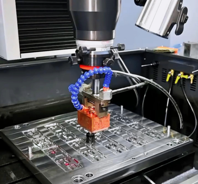
Which mold and die features depend on EDM?
Sharp corners, narrow ribs and precise clearances.
Mold cavity details, die apertures, engraved forms and the clearances between mating tool components are the features that usually make discharge machining unavoidable.
In a plastic mold, the features that require EDM are typically the corners and narrow details of the cavity, deep ribs in a tall part, engraved lettering or texture, and the shut-off surfaces where two mold components meet and must seal against each other. Those shut-offs are often the most demanding, because they must hold a tight clearance after heat treatment, and the geometry frequently includes corners that no cutter can reach.
In a die, the same pattern appears at a different scale. Apertures and profiles are wire-cut for accuracy; reliefs, engraving and three-dimensional detail are sunk with electrodes. Extrusion dies, stamping dies and forging dies all combine the two.
Where a design does not genuinely require a sharp corner, relaxing it is the cheapest improvement available. A small radius that a cutter can produce removes an entire operation from the routing, and it also reduces stress concentration in the tool, which improves its service life. That trade is worth examining at the design stage rather than discovering it after the tool has been cut.
How do cost and schedule change when processes are mixed?
Each process adds a setup, and the sequence adds risk.
A part that is milled, heat treated and then finished by EDM carries three operations and two transitions, and the schedule depends on how well those steps are sequenced rather than on any single machine.
Mixed routing is normal for tooling, and its cost is cumulative. Roughing in the soft state is fast and cheap. Heat treatment adds a lead time that is often outside the machine shop’s control. Finishing by EDM adds machine time plus electrodes. Inspection closes the loop. Each step has its own queue, and the transitions between them are where schedule risk accumulates.
| Step | What happens | Why the order matters |
|---|---|---|
| Rough machining | Bulk material removed in the soft state | Fast, and leaves finishing allowance |
| Heat treatment | Hardening and tempering to final hardness | Changes dimensions and introduces distortion |
| Finish machining | Accessible features cut after treatment | Accuracy is not destroyed by quenching |
| EDM finishing | Corners, ribs and clearances produced by discharge | Geometry that a cutter cannot reach |
| Surface finishing | Recast layer removed where it is functional | Affects fatigue behaviour and coating adhesion |
| Inspection | Dimension and fit checked against the drawing | Confirms the sequence produced the feature |
Two practices reduce that risk. The first is to make allowance explicit, so that the finishing operation has enough material to work with after heat treatment. The second is to keep the operations within one supplier, where the sequence, the references and the responsibility are held together. 6CProto runs CNC machining and EDM alongside each other, which is what allows the routing to be planned as one program rather than negotiated between shops. Where the process produces waste streams, such as used dielectric fluid and eroded sludge, those are handled under the industrial waste framework published by the US Environmental Protection Agency.
Where the cost of mixing is too high, the alternative is to reconsider the design. A feature that requires EDM after hardening may be replaceable by a separate insert, machined in a softer material and assembled into the tool. That kind of substitution is a design decision, and it is cheapest when it is made before any of the operations begin.
Planning for hard-material features
The decision to use discharge machining on hardened steel is usually made for you by the geometry. Where a feature has a sharp corner, a deep narrow form or a tight clearance that must survive heat treatment, EDM is the process that produces it. Where the feature can be cut with a tool, milling remains faster and cheaper even at high hardness, and the design should be reviewed with that trade in mind.
The specification that gets a good outcome is short. State the material and its condition, the features that must be produced after heat treatment, the tolerance and finish that are functional, and the sequence you expect. That information lets the shop plan roughing, electrodes and finishing passes as one route. The comparison with conventional machining is covered in more depth in the 6CProto article on EDM and precision machining for complex metal features, and the materials context for hardened steels is documented by bodies such as ASM International.
FAQ
What are the disadvantages of EDM?
It removes material slowly compared with milling, so it is used for finishing features rather than clearing stock. Sinker work consumes electrodes, and wear affects accuracy on deep cavities. The cut surface carries a recast layer whose thickness depends on the finishing passes. And it requires conductive material, so it cannot produce non-metallic components. Most of these limits are manageable through process planning rather than design change.
What materials can an EDM cut?
Any electrically conductive material, which covers the tool steels, stainless steels, carbides and nickel alloys used in tooling and precision parts. Behaviour varies: some alloys erode faster than others, and the recast layer differs with material and with the discharge settings. What does not vary is the fundamental independence from hardness, which is why the process is used on parts that are already heat treated.
How thick can you wire an EDM?
Wire machines cut substantial thicknesses, well beyond what a thin die plate requires, and the practical limit depends on the machine, the flushing arrangement and the accuracy demanded rather than on a single figure. Thicker parts take longer, since the cut length is the same but the wire travels through more material, and taper capability tends to reduce as thickness increases. For a specific part, the achievable combination is worth confirming at review stage.
Should a tool be heat treated before or after EDM?
Normally before, for the features that rely on EDM’s accuracy. Quenching changes dimensions and introduces distortion, so any fine feature produced before heat treatment risks moving out of position. The common sequence is to rough the part in the soft state, heat treat to final hardness, then finish critical features by discharge machining. That order also reduces the amount of material the EDM operation has to remove.
If a hardened part has features that a cutter cannot reach, send the drawing with the material condition and the heat treatment sequence. 6CProto reviews tooling geometry, plans roughing and finishing around the heat treatment, and returns a DFM report with the quote. Upload the file at the 6CProto quote page or send it to projects@6cproto.com.