

An electronics enclosure needs airflow, and the first design cuts a row of rectangular holes in the panel — which solves the heat problem and creates an EMI and dust problem. Vents in sheet metal are a trade between airflow, shielding, protection, and cosmetics, and the trade is decided by the vent geometry. Louvers punch and form a louver that opens an airflow path while blocking a direct line of sight; perforations and grilles offer different balances of open area, strength, and shielding. The vent design should start from the requirement — how much air, what protection, what shielding — and then choose the geometry that meets it.
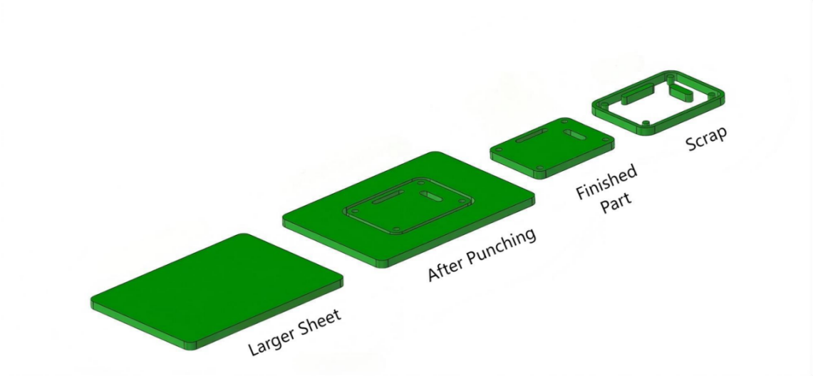
Louver geometry: length, pitch, and material limits
A louver is a punched-and-formed flap that stays attached at one end, creating a slot for airflow. Its geometry is set by the louver length, the pitch between louvers, the louver height or opening, and the material thickness. Longer louvers move more air but weaken the panel and can distort; a tighter pitch increases open area but leaves less material between the cuts; and the louver height is limited by the material’s formability and the tooling. The louver should be oriented so airflow moves in the intended direction and so water or debris does not enter where the enclosure must stay protected. The material and thickness set the practical louver size, and the punch tooling sets the achievable geometry.
Louver rows should be designed with the panel’s structural role in mind: a large vent area in a load-bearing panel can reduce its stiffness, and the louver field should be placed where the airflow is needed without removing the material the structure depends on.
Punch-and-form tooling considerations
Louvers are produced by a punch-and-form tool that cuts and forms in one stroke, and the tooling sets the geometry limits: the louver length is limited by the tool, the louver direction is set by the tool orientation, and the louver height is limited by the material’s formability. The design should confirm the louver geometry against the available tooling before the drawing is released, because a louver that the tool cannot form becomes a custom tool or a design change. The tooling also leaves the louver edges with the punch’s condition, and the burr direction should be considered for safety and for the finish.
If the enclosure is low volume, the louver tooling cost should be weighed against simpler vent options; a custom louver tool for a few parts is rarely justified, and perforation or a separate vent grille may serve the requirement at lower cost.
Airflow, EMI, and cosmetic trade-offs of vent patterns
The vent pattern trades airflow against shielding and appearance. Open area drives airflow, but open area also opens the enclosure to electromagnetic interference and to dust and water. Louvers block a direct line of sight, which helps optical and some EMI requirements, but they do not provide the shielding of a waveguide-style array or a filtered vent. Perforated sheet offers predictable open area but less directional protection, and the hole pattern can be tuned for airflow and appearance. The design should state the airflow requirement and the shielding or protection requirement together, because a vent that maximizes airflow alone will fail the other requirements, and a vent that maximizes shielding alone will cook the electronics.
Cosmetics are part of the trade: vent patterns are visible, and the hole or louver pattern should be laid out consistently across the panel rather than appearing as an afterthought. The pattern pitch, the margins, and the edge distance should be designed, not left to the shop’s default spacing.
Alternatives: perforated sheet, grilles, and separate vents
Louvers are not the only answer, and the alternative often fits the requirement better. Perforated sheet provides controlled open area with a clean appearance and is available in standard patterns; a separate vent grille can be molded, printed, or machined and attached over a cutout, adding design freedom for airflow and appearance; and a filtered vent adds dust protection where the environment demands it. The choice is a cost and function trade: louvers are formed into the panel with no added part, perforation can be done on the sheet, and a separate grille adds a part and an assembly step but allows a different material and geometry. The vent design should compare the routes against the airflow, protection, and appearance requirements before the panel is cut.
For enclosures that must meet an ingress rating, a louvered or perforated opening usually needs a filter or a baffle to block water and dust, and the protection rating is earned by the whole vent assembly, not by the hole pattern alone.
Drawing and tolerance notes for vent features
Vent features need drawing notes that state the pattern, the geometry, and the direction: the louver size and pitch, the louver opening direction, the vent area or the airflow requirement, and the margins around the pattern. The tolerance on vent geometry is usually functional rather than tight — the open area and the pattern consistency matter more than the exact louver height — and the drawing should say which dimensions matter. Mark the vent field so the shop does not relocate it, and note the burr direction or the finishing requirement if the vent edges are visible or must be smooth. A vent specified as a field with a requirement, not as a collection of holes, is a design feature that the shop can produce and inspect consistently.
The sheet-metal fabrication service and the punching capability pages cover the process; the vent design rules above are what turn an opening into a controlled airflow and protection feature.
Choosing the vent route from the requirement
A vent selection example shows the trade in practice. An outdoor electronics enclosure needs airflow for a 15 W thermal load and must keep out direct spray. The first option, a louver field, provides airflow and blocks a direct line of sight, but the louver tooling is a one-time cost and the open area is limited by the panel geometry. The second option, a perforated panel, offers predictable open area at lower tooling cost but lets spray and dust through the holes. The third option, a cutout with a filtered grille, adds a part and an assembly step but provides the airflow, the protection, and the cleanable filter that the environment needs. The design team compares the routes against the thermal load, the ingress requirement, and the volume: at high volume the louver tool pays for itself; at low volume the grille route avoids the tooling; and where the ingress rating matters, the filtered grille is the only route that meets it. The example is the vent decision in miniature: the geometry is chosen from the requirement, not from the habit of cutting holes.
The requirement should be quantified before the route is chosen: the airflow or the thermal load, the protection level, the shielding need, and the appearance class. Each route has a cost and a performance profile, and the drawing should state the requirement so the shop can recommend the geometry. When the vent is designed as a system — the pattern, the tooling, the protection, and the finish — it becomes a controlled feature rather than a field of holes. The louver and vent notes on the drawing should carry the pattern, the direction, and the requirement, so the shop produces the airflow the enclosure needs and the protection the environment demands.
Airflow math comes before the geometry. The vent design should start with the thermal load and the allowable temperature rise, which set the airflow requirement, and the airflow requirement sets the open area, which the louver or perforation pattern must deliver. Without the math, the vent is sized by habit and the enclosure either runs hot or carries more open area than the protection allows. The open area calculation should also account for the real flow behavior — louvers and perforations restrict flow, and the effective open area is lower than the geometric area — so the pattern should be sized with a margin and verified with the thermal test. The same discipline applies to the protection and shielding requirements: the pattern that meets the airflow target is then checked against the ingress and EMI limits, and the route is adjusted until all three fit. The vent is a system designed from the numbers, and the drawing carries the requirement so the shop produces the pattern that meets it.
The vent pattern also deserves a visual check before tooling. A prototype panel with the louver or hole pattern lets the team confirm the airflow direction, the appearance, and the protection before the production tool is committed. The prototype is cheap relative to a tooling change, and it answers the questions that drawings cannot: how the pattern looks on the real panel, how the airflow feels at the target, and whether the protection blocks the spray as intended. The prototype review is the last gate before the vent design is locked, and it is the step that turns a calculated pattern into a verified one.
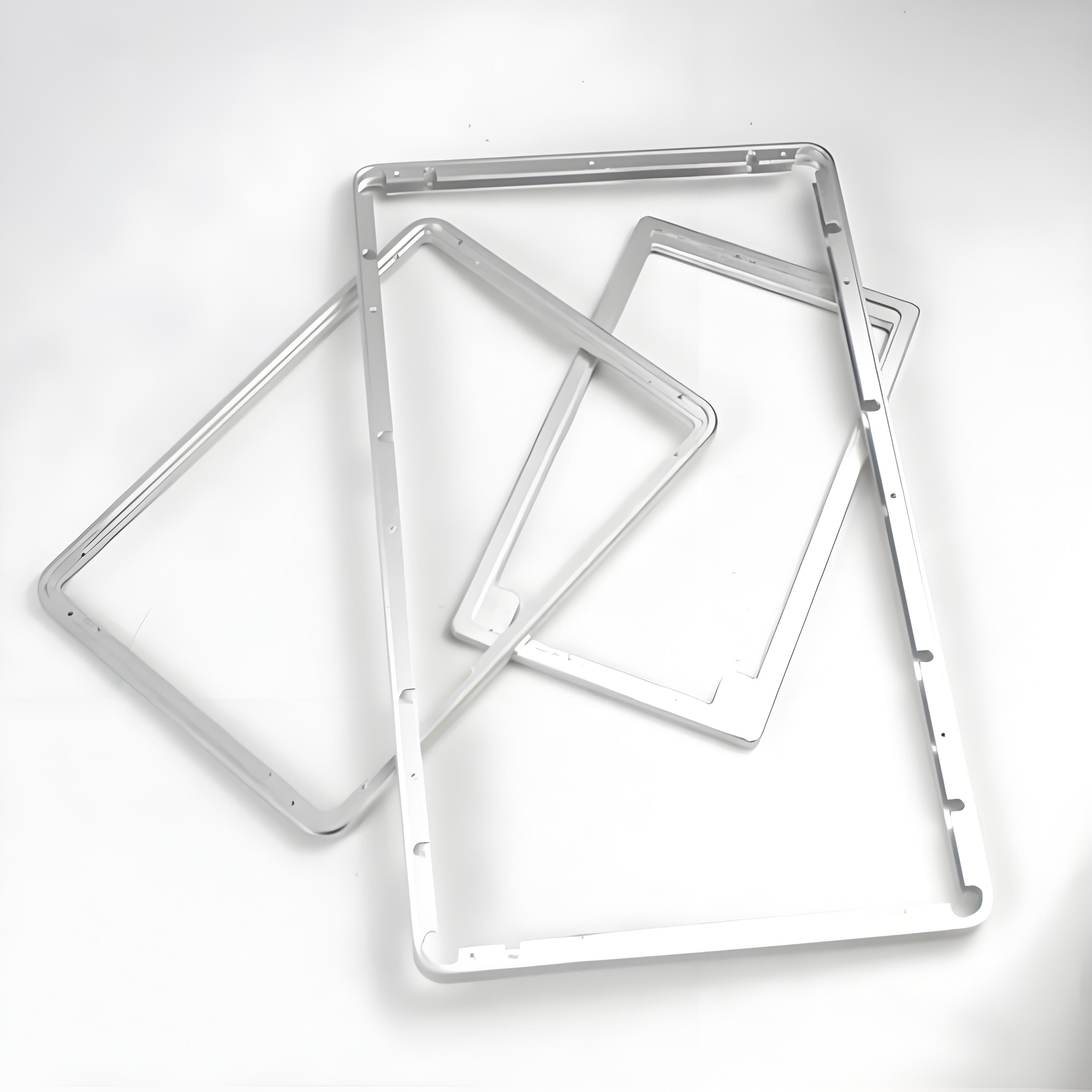
If you are designing vents for an enclosure and want the airflow, shielding, and protection trade reviewed against the geometry, the 6CProto sheet metal team can work from the requirement to the louver, perforation, or grille recommendation.