

A molded plastic housing with a screw boss cracks on assembly, and the next part’s screw strips because the boss wall is too thin and the pilot hole is wrong. The boss is the feature that carries the screw in a molded plastic part, and its design — the outer diameter, the pilot hole, the counterbore, and the connection to the wall — decides whether the screw drives cleanly, holds its load, and survives disassembly. Thread-forming screws are common in plastic because they cut or form their own thread without inserts, but they demand a boss geometry that is designed for the material and the screw, not copied from a metal part.
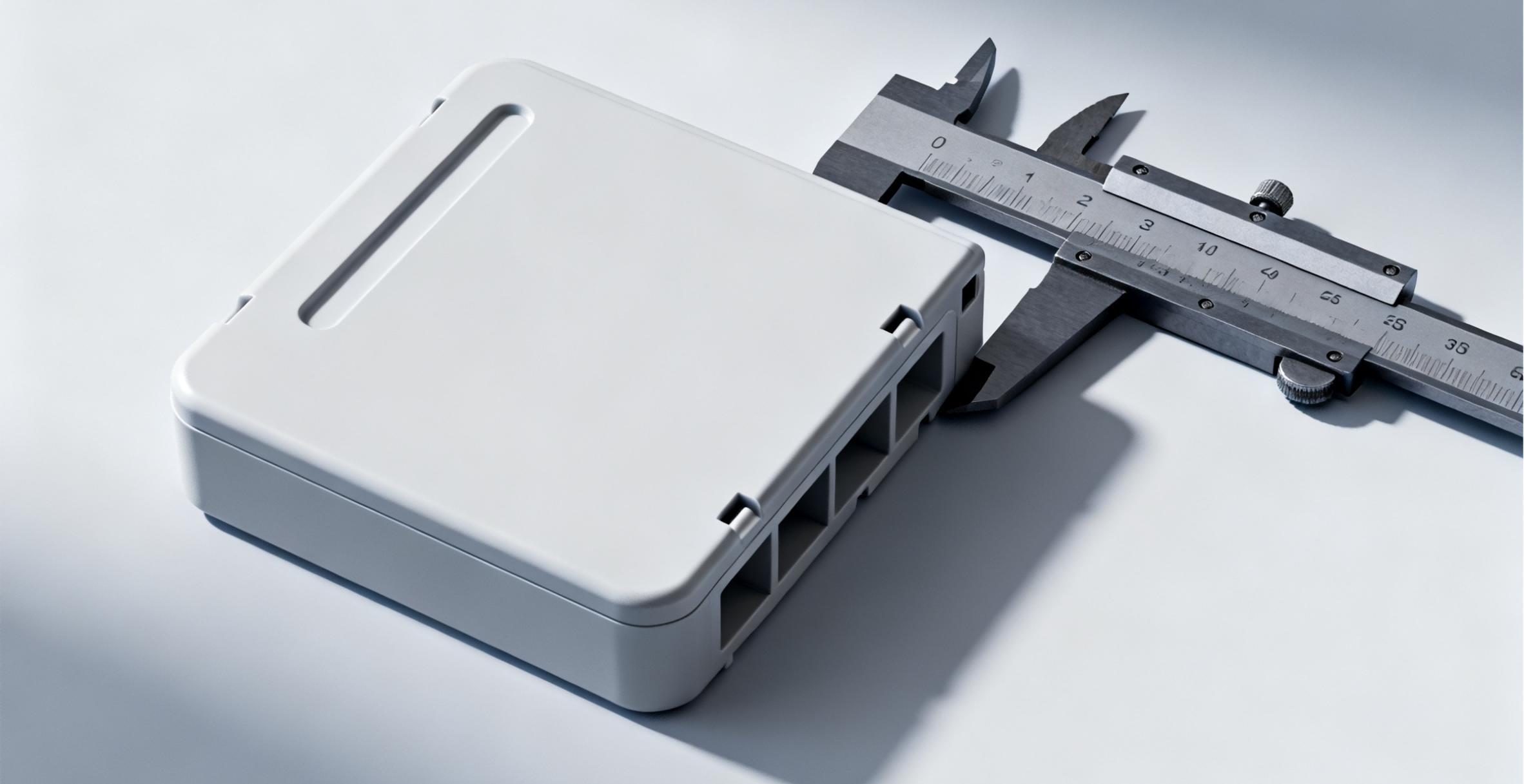
Boss functions: piloting the screw, carrying load, resisting pull-out
A screw boss does three jobs. It pilots the screw, guiding it straight into the hole so the thread forms cleanly; it carries the clamp load between the screw and the part; and it resists pull-out when the joint is loaded. Each job sets a dimension: the pilot hole sets the thread-forming and the alignment, the boss wall carries the clamp and the pull-out load, and the boss height provides the thread engagement. A boss that is too small for the screw strips or pulls out; one that is too large sinks on the visible surface opposite it. The design starts from the screw size and the load, and each boss dimension follows from them.
The boss also interacts with the wall it attaches to: a boss standing alone on a thin wall flexes under the screw load, and the connection to the wall carries the load into the part. The boss and the wall are designed as one feature.
Sizing the boss: outer diameter, pilot hole, and counterbore basics
The boss dimensions follow the screw and the material. The pilot hole diameter is set for the thread-forming screw — large enough that the screw can start and form its thread without cracking the boss, small enough that the thread engages with enough material. The boss outer diameter provides the wall that carries the thread and the clamp load; a common starting point is an outer diameter about twice the screw’s major diameter, with the wall thickness tuned for the material. The counterbore or the chamfer at the hole entry guides the screw and prevents cross-threading. The dimensions should come from the screw supplier’s recommendations for the material, because the thread-forming behavior is specific to the screw and the resin.
The boss height should provide the thread engagement the load needs, and the boss should be sized so the screw does not bottom out or break through the far side.
Material-dependent cautions for thread-forming screws
Plastics respond differently to thread-forming screws. Soft, ductile materials form threads readily but may strip under repeated assembly; stiff, brittle materials crack if the pilot hole is too small or the wall is too thin; and filled materials wear the screw and change the thread-forming behavior. The boss design should be confirmed with the actual material grade, because the pilot hole and the wall that work in one resin can fail in another. The screw type also matters: some thread-forming screws are designed for specific plastics, and the screw supplier’s data provides the hole and the boss guidance for the pair. The material and the screw are a system, and the boss is designed for the system.
The assembly torque is part of the system: a torque that is too high strips the boss threads, and the assembly instruction should set the torque for the material and the boss.
Gussets and wall connections that stop boss collapse
A boss that is tall or loaded needs gussets — thin ribs that connect the boss to the wall and carry the screw load into the part. The gussets prevent the boss from flexing or collapsing under the clamp load, and they are sized like ribs: thin enough to avoid sink marks, connected with a radius to avoid stress concentration. The gusset pattern should be designed for the load direction: a boss that carries a bending load needs gussets in the load plane, while a boss that carries only the clamp load needs less support. The boss-and-gusset package is drawn as one feature, with the gusset thickness and the connection radius specified.
The gussets also help the molding: they stiffen the boss during ejection and reduce the stress concentration at the boss-to-wall junction. The design should confirm the gussets do not create the thick section that sinks on the visible face.
Drawing a boss package a molder can hit
The boss package on the drawing should carry the full set: the boss outer diameter, the pilot hole and its depth, the counterbore or chamfer, the gusset dimensions, and the screw specification. The draft angle on the boss is included for the molding, and the wall connection is dimensioned so the molder produces the feature the design intends. The critical dimensions — the pilot hole and the boss wall — are marked for inspection, and the assembly torque is noted. A boss that is dimensioned completely is a feature the molder can hit and the assembly can trust; one that is left to the shop’s default is a feature that varies with the mold maker and the molder. The boss design guide is the single-feature version of the DFM rules, and it is the difference between a screw joint that works and one that cracks, strips, or sinks.
Validating the boss on the first parts
The boss design should be validated on the first molded parts before the production tool is committed. The first-article review drives the screw into the boss with the production torque, checks the thread formation and the pull-out resistance, and looks for the failure modes — a cracked boss, a stripped thread, or a sink mark on the visible surface opposite the boss. The validation results decide whether the boss dimensions are right for the material and the screw, and the adjustments are made while the tool changes are still cheap. A boss that is validated on the first parts is a boss the production run can trust; one that is released from the drawing without the test carries the risk into the full run, where the failure costs more than the validation would have.
The validation should also cover the assembly variation: the screws from the production supplier, the torque from the production tool, and the material from the production lot. The boss that works with one screw lot and one torque setting can fail when the variation stacks, so the validation should test the extremes or the sample size should give the margin. The assembly instruction should carry the torque and the screw, and the inspection should check the boss features at the interval that catches the drift. When the boss is validated and controlled, the screw joint is a designed feature with a test record — and the assembly that works on the first article is the assembly that works in production.
The boss design should also be reviewed against the molding process, because the boss is a molded feature with its own forming requirements. The boss needs draft so it releases from the mold, and the draft reduces the wall from the base to the top, changing the strength and the thread engagement. The boss should be gated or filled so the material reaches the top without a weld line or a short shot, and the boss at the end of the flow path may need the gate or the vent adjusted. The sink mark on the surface opposite the boss is a molding concern: the boss adds material to the wall, and the visible face can sink unless the boss wall is thin enough or the surface is textured or the design accepts the mark. The molding review of the boss should consider the fill, the venting, the draft, and the sink, and the boss geometry should be adjusted so the feature molds cleanly as well as holds the screw. A boss that is designed for the screw but not for the molding is a feature that the mold will fight, and the fight shows up as the sink, the short, or the warp that the drawing never intended.
Keep the boss specification with the tooling record so the first article and the production runs are measured against the same feature. The boss is a small feature with a large effect on the assembly, and the record is what keeps it consistent.
Confirm the pilot-hole and boss dimensions with the screw supplier’s data for the exact plastic grade, and verify them on the first molded parts before the full run. The supplier data plus the molded sample is the evidence that the boss will hold its screw.
If you are designing screw bosses for a molded plastic part and want the hole, the wall, and the gusset package reviewed for your screw and material, the 6CProto injection molding team can work from your joint load to the boss specification before the tool is cut.