

Consider two illustrative RFQ packages for the same housing. Both include a DXF outline, but only one also defines the formed shape, material, bend direction, hardware, finish, and critical assembly interfaces. The second gives a fabricator a reviewable product definition. This hypothetical comparison explains what custom metal housings from 2D drawings need beyond an apparently complete cutting file.
Why DXF alone is not enough
For custom metal housings from 2D drawings, supply the controlled formed-part definition, material and thickness, bend information, hardware, finish, quantities, and acceptance requirements alongside the DXF. Identify which file governs each requirement and keep revisions aligned. A flat cutting profile cannot by itself define the completed housing or its assembled interfaces.
In the first illustrative package, a fabricator can see outlines and holes but must still ask which lines are cuts, marks, or bends. The other package identifies those layers, units, orientation, and the intended formed result. The difference is missing information, not a claim that one file format is unsuitable.
Autodesk’s flat-pattern DXF export documentation describes units and separate exported geometry layers. Review those export choices rather than assuming every receiving program interprets the file identically. State the role of the DXF in the approved drawing pack.
Bend notes and K-factor assumptions
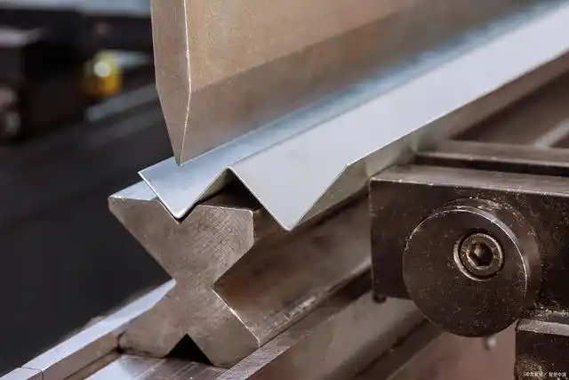
Define the formed dimensions, bend direction, angle convention, inside radius requirements, and relevant reliefs. Identify critical relationships across bends, such as mounting holes that must align after forming. If only a flat blank is ordered, state that different deliverable explicitly.
Ansys’s bend-allowance documentation explains the K-factor concept and the need to relate it to the actual bending setup. A CAD default is not a universal material constant. Agree who develops or verifies the manufacturing flat pattern against the specified formed geometry.
TRUMPF’s bending overview provides process context for that review. Tooling, access, sequence, and material behavior matter in making the physical shape. Ask the fabricator to flag conflicts before cutting, rather than allowing an assumed allowance to become an unexplained change to the final envelope.
Hardware and finish callouts
Identify installed hardware by full part reference or approved specification, quantity, orientation, and location. Show access for installation and for the mating fastener. A note saying inserts required cannot establish the host-sheet geometry or the assembled protrusion.
PennEngineering’s surface-finishing guidance for assemblies addresses interactions between panel treatment and self-clinching hardware. Agree the finish and installation sequence for the selected parts. Neither finishing everything first nor installing everything first is a universal rule.
Specify the coating or treatment, masked regions, color and texture criteria, and any grounding or mating surfaces that need a different condition. State which dimensions are accepted after finishing. If an appearance sample governs color or texture, identify it and the viewing conditions rather than relying on a file name or an uncontrolled photograph.
Table: file checklist
The richer illustrative package does not need redundant documents for their own sake. Each item should close a requirement that the cutting profile leaves open. Reconcile conflicts before the supplier begins manufacturing.
| Item | What it should establish | Cross-check |
|---|---|---|
| Controlled formed drawing | Final dimensions, tolerances, material, finish and notes | Same revision as the approved product definition |
| DXF or equivalent flat geometry | Units, contours and defined geometry layers | Cutting and marking roles; no conflicting duplicate contours |
| 3D model where available | Intended shape, orientation and access | Agreement with controlling dimensions and assembly |
| Hardware list | Part identity, count, position and orientation | Host sheet, installation access and protrusion |
| Assembly definition | Mating parts, joints and critical interfaces | Fit after forming, joining and finishing |
| Inspection request | Accepted features, state and required records | Methods appropriate to the final component |
ASME Y14.5 supplies geometric communication rules under the chosen drawing convention. Use appropriate references for the finished housing instead of relying on unrelated flat-pattern edges to imply assembly fit.
Prototype iteration tips
Use the first sample to resolve named uncertainties: bend access, mounting alignment, cover fit, hardware clearance, surface appearance, or the fit to an adjacent component. A prototype that merely resembles the model does not necessarily answer those questions.
Record the differences between the initial and revised package. Update the formed drawing, model, DXF, and hardware list together where each is affected. Keep the supplier-approved manufacturing information traceable to the product revision, especially when a bend allowance or relief changes.
In the illustrative comparison, the useful outcome is fewer unresolved assumptions, not a guaranteed reduction in price or delivery time. Ask the supplier to return proposed changes for approval. Do not let a trial adjustment become a silent alteration to the controlling product geometry.

FAQ
These questions address specification details that should be settled before sample approval.
Can a DXF be used when no 3D model is available?
Yes, provided the coordinated drawing pack defines the required formed shape, material, bends, hardware, finish, and acceptance criteria. Identify missing information and agree any modeling or manufacturing-flat development with the supplier. A 3D file is useful context, but an undefined product remains undefined in any format.
Should the supplier always use the CAD default K-factor?
No. The manufacturing allowance needs to suit the actual material, thickness, tooling, bend method, and setup. Agree responsibility for the flat pattern and verify the required formed result. A software default is not a substitute for that review.
Which file should control if the DXF and drawing disagree?
State the document hierarchy and each file’s role in the procurement package, then resolve the actual conflict before manufacture. Do not expect the supplier to choose whichever interpretation is easiest. Keep the approved drawing, model, flat geometry, and revision record coordinated.
Related process selection notes
Confirm whether the housing is sheet-metal fabricated, machined, or a hybrid. The machined enclosures and housings review addresses a different route from producing and bending a flat sheet. A file containing a two-dimensional profile does not settle that process choice.
For the fabricated route, coordinate laser cutting with forming and bending. Include hardware, joins, and finish where required. Identify which features need a secondary operation to meet the final requirement.
Compare complete delivered scopes. A flat blank and a finished housing are different quotation items even if they originate from the same DXF. State the configuration and the required inspection so the supplier can price the actual order.
Internal links and next steps
Send the coordinated file pack, quantity, critical interfaces, finish requirements, and evidence request to the sheet-metal fabrication review. Identify missing information and any permitted design alternatives without asking the fabricator to invent the product specification.
Check the quotation response for file revision, material, delivered state, hardware, finish, inspection, assumptions, and exclusions. Resolve conflicts before authorizing manufacture. Preserve the approved package as the reference for sample acceptance and repeat orders.
Request a 6CProto housing quotation with the DXF and complete formed-part requirements. Use the first-sample review to confirm the interfaces that the flat profile alone could not establish.