

Consider two illustrative electrical-assembly reviews. A current-carrying link needs its resistive heating assessed, while a threaded support mainly needs to retain a mechanical interface. Selecting the same easy-to-machine metal for both can hide the requirement that matters. This copper vs brass CNC comparison follows those two decisions; it is not a report of a customer project.
Conductivity vs strength needs
For copper vs brass CNC electrical parts, specify the exact alloy and temper, then compare current-path resistance, mechanical requirements, machinability, contact surfaces, and environmental exposure. High-conductivity copper and free-cutting brass serve different priorities. Validate the finished connection under its assembly conditions instead of using a material name or plating appearance as electrical proof.
In the first illustrative review, the link’s bulk resistance depends on resistivity and geometry, while its connections introduce additional contact behavior. Increasing a cross section or changing an alloy can affect the bulk path without resolving a poor interface. Keep current, duty, permitted temperature rise, and installed cooling conditions in the design assessment.
The Copper Development Association lists C11000 as a high-conductivity copper and identifies C36000 as free-cutting brass with different conductivity and composition. Compare the specified condition and product form. A mechanical support that carries little current has a different selection problem from a conductor constrained by heating.
Machinability and burr behavior
The second review starts with machining and assembly: threads, shoulders, bore position, and the required retention. Brass may be a candidate where its actual grade satisfies those functions, but free-cutting brass is not a substitute for every copper conductor. Confirm any composition restrictions as part of material selection.
The German Copper Institute’s machining guide distinguishes copper-alloy machinability and discusses chip formation, tools, and operations. Its comparative ratings are guidance, not a direct multiplier for the quotation or a promise of burr-free production.
Identify delicate contact edges, small holes, narrow slots, and threaded exits. Ask how the chosen route controls burrs without rounding a functional contact or changing an edge that establishes fit. A broad instruction to deburr all edges leaves too much interpretation where the contact area or electrical clearance depends on the delivered geometry.
Plating and oxidation notes
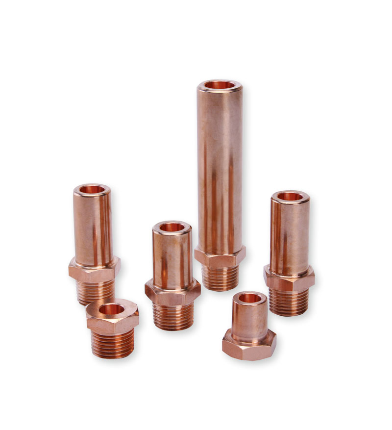
Both reviews must return to the delivered surface. Identify the contact region, plating stack where specified, masking, appearance criteria, and any requirements for storage or handling. An unqualified instruction to plate the part does not define a reproducible contact interface.
SAE’s connector-finishing compatibility guidance addresses compatible finishes and corrosion considerations in its EWIS scope. It supports reviewing the mating pair and exposure together; it does not establish an appropriate plating system for every electrical product.
Evaluate oxidation, corrosion, contact loading, and mating cycles as the actual assembly requires. Plating can change the interface condition, but it does not transform the entire substrate into a high-conductivity copper conductor. Define which electrical checks belong to the finished part and which belong to the assembled connection.
Table: copper vs brass decision
The review sequence is simple: identify the dominant function, shortlist specified alloys, check manufacturability and finish, then validate the actual interface. Use the table to keep the conductor and support decisions distinct without assuming that either material family always wins.
| Requirement | High-conductivity copper candidate | Brass candidate | Acceptance evidence |
|---|---|---|---|
| Low bulk resistance | Evaluate specified conductivity and geometry | Check whether the actual alloy meets the resistance budget | Approved calculation and required electrical test |
| Threaded support | Verify strength, thread condition and retention | Evaluate grade-specific mechanical and machining fit | Dimensional and assembly checks |
| Detailed machined features | Review chips, edges and surface condition | Review actual grade and composition constraints | Representative sample inspection |
| Mating electrical contact | Define finish and contact conditions | Define finish and contact conditions | Assembly-specific contact and exposure evidence |
The outcome may be different materials for different components. A uniform purchasing description can simplify paperwork while making the engineering requirements less clear.
Drawing callouts
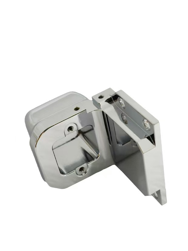
State the alloy designation, temper, product specification, quantity, critical interfaces, finish, and required documentation. Mark the current-carrying path and the contact faces so their significance remains visible during manufacturing review. Identify any permitted substitutions and their approval authority.
ASME Y14.5 provides geometric communication rules for the drawing’s chosen convention. Use appropriate relationships for locating contacts, mounting holes, and mating shoulders. Roughness, flatness, position, and plating requirements should each describe a functional need.
For the two illustrative components, the conductor’s review would include resistance and contact acceptance, while the support’s review would emphasize its locating and retention interfaces. Both still need the relevant material and finish controls. Avoid replacing those controls with a generic electrical-grade label.
FAQ
These questions address specification details that should be settled before sample approval.
Can brass replace copper in a current-carrying part?
Only after engineering review of the specified alloy, geometry, current, contact arrangement, temperature rise, and environment. Brass grades have different conductivity and mechanical characteristics from high-conductivity copper. Ease of machining alone does not establish that the replacement meets the electrical requirement.
Does plating remove the need to specify the substrate alloy?
No. The substrate still affects bulk conductivity, mechanical behavior, machining, and finish compatibility. Define both the base material and the delivered coating system, then evaluate the actual mating connection where electrical contact performance matters.
Can machinability ratings predict the unit price?
No. Comparative ratings do not include every feature, stock form, setup, burr-removal operation, finish, inspection, or order quantity. Use them as background for a route-specific discussion and compare quotations with the same material and acceptance requirements.
Related process selection notes
Review turning for rotational features and milling for flats, slots, or non-rotational contacts as the geometry requires. The CNC machining discussion should explain the complete route, including secondary operations and inspection. Stock shape, setup count, and edge control can matter alongside the alloy’s cutting behavior.
Use the copper material page and brass material page to begin the sourcing conversation. Confirm the exact offered grade and condition in the quotation. A photograph cannot identify the alloy, temper, conductivity, or plating stack of a newly ordered component.
The lesson from the illustrative review is to finish the functional comparison before optimizing the machining route. Easier cutting is useful only when the resulting part still meets its electrical, mechanical, and environmental requirements.
Internal links and next steps
Send CAD, the controlled drawing, quantity, material candidates, plating details, and the required evidence. Include current and exposure requirements only where they inform the design and acceptance scope; keep the responsible engineering assessment explicit.
For a consumer-electronics assembly, identify the actual contact, support, and enclosure interfaces. Ask the supplier to flag burr-sensitive geometry, finish allowances, and proposed substitutions. Approve changes against the relevant function rather than an alloy-family preference.
Request a 6CProto copper or brass quotation with the contact and mechanical requirements. Compare the specified delivered parts and the required validation together.