

The prototype is finished on paper and the question is no longer whether the geometry works, but whether it can be cut, measured and repeated. That is where most first articles lose a week: the drawing is complete but the process route, the holding method and the inspection plan have not been decided. CNC rapid prototyping closes that gap by machining the geometry directly from a solid model, so the part you test is made of the material you intend to ship.
Which CNC route actually fits this part
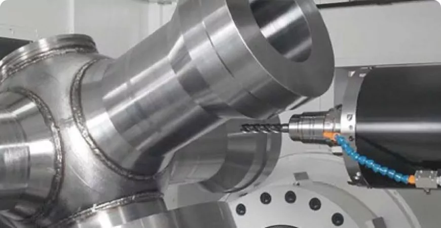
Route selection follows geometry, not preference. Turning suits parts that are mostly rotational, milling handles pockets and planar faces, and 5-axis machining wins when a part has features on several faces that would otherwise need multiple re-fixturings. Precision machining is a discipline applied across all three rather than a separate machine. For a first article, the deciding question is how many distinct setups the part needs: every extra setup adds a datum transfer and a fresh chance for position error.
| Part geometry | Likely route | What to watch |
|---|---|---|
| Shafts, bushings, fittings, connectors | CNC turning | Concentricity between turned diameters; bar stock size |
| Plates, brackets, housings with planar features | 3-axis milling | Tool reach into pockets; floor and wall finish |
| Impellers, angled ports, contoured faces | 5-axis machining | Collision checking and fixture clearance |
| Hardened tooling and sharp internal corners | EDM | Electrode design and burn time |
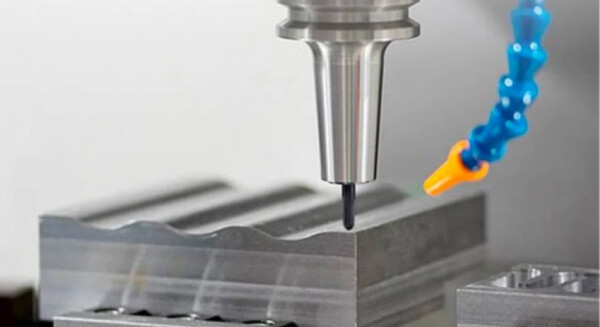
Tolerances and surface finish you can actually hold
The achievable tolerance on a prototype is a function of the feature, the fixturing and the material, which is why blanket tolerance notes on a prototype drawing usually raise the price without improving the part. A diameter turned between centres behaves differently from a thin wall milled in a long pocket, and a soft plastic moves under the same cutter load that leaves stainless steel stable. Specify tight limits only on the dimensions the assembly actually reads.
Surface finish works the same way. As-machined faces carry visible tool marks; a brushed, bead-blasted or plated finish changes appearance, corrosion behaviour and sometimes the fit itself, because coatings add material. If a mating surface is also the show surface, call that out so finishing is planned after the critical dimensions are verified. Our guidance on standards and tolerances covers how to state that on a drawing.
DFM checks that change the design before cutting starts
A design-for-manufacturability review is worth more before the first chip than after the third revision. The checks that most often change a prototype are tool access, holding strategy and the relationship between a feature and its measurement. Internal corners need a radius at least as large as the cutter, deep pockets need clearance for the holder as well as the tool, and a feature that cannot be reached by a probe cannot be verified without a special setup.
- Corner radii sized to a standard cutter so the feature does not need a second operation.
- Wall thickness and rib depth checked against cutter deflection, especially in plastics.
- Threaded holes, dowel positions and datums placed so they can be reached in one clamping.
- Any cosmetic surface marked, so finishing is not applied across a functional fit.
6CProto runs this review as part of quoting: models in STEP, STP, IGES, IGS, SLDPRT, 3DM, SAT or X_T are checked for manufacturability and returned with comments before production starts.
What drives the price of a first article
Quoted price is dominated by time that is charged once and then divided across the batch, which is why unit cost falls sharply as quantity rises and why a single complex part can cost more than a small run of simple ones. Programming, fixturing, first-article inspection and any custom finishing setup sit in that fixed block. Material cost scales linearly and is rarely the largest line on a prototype quantity.
Upload your CAD file to get a DFM review and quotation, or send drawings to projects@6cproto.com to discuss a first article.
Quality control and the inspection plan
Inspection should be defined before the part is made, because it determines what the machining setup must protect. On a prototype, the practical sequence is material verification, in-process checks on the dimensions that drive fit, and a final dimensional report on the drawing callouts. Where a feature is difficult to reach, a CMM report on a defined datum scheme tells you far more than a set of manual measurements taken at inconsistent references. Inspection reports are available on request for 6CProto orders.
Materials and machinability trade-offs
Material choice sets the achievable finish, the minimum wall thickness and often the process itself. Aluminium machines quickly and takes finishing well; stainless steel holds threads and resists wear but is slower; engineering polymers such as PEEK, PEI and POM machine cleanly but deflect and generate heat if feeds are wrong. Because the prototype is meant to predict production behaviour, choose the material the production part will actually use whenever the test is mechanical rather than purely dimensional. The CNC machining materials library lists the grades stocked across metals and plastics.
How to brief a supplier in one page
A prototype brief does not need to be long, but it does need to remove the assumptions a shop would otherwise make on your behalf. Three of those assumptions recur: whether a surface is cosmetic or functional, whether the quantity quoted is a one-off or the first of several releases, and which features are allowed to move if the process cannot hold everything at once. Answering them in writing costs a few minutes and usually removes a round of questions.
The rest of the brief is mostly an index. List the material with any condition or temper, name the finishing requirement and where it applies, state the inspection expectation, and mark the datums you intend to measure from. If a prototype is destined for a regulated product, say so early, because it changes which records have to be generated alongside the parts rather than afterwards. Guides that cover how requirements are stated on a drawing are collected under standards and tolerances, and models can be submitted in STEP, STP, IGES, IGS, SLDPRT, 3DM, SAT or X_T.
FAQ
How much does CNC prototyping cost?
Cost tracks machining time plus setup, not part count alone. One complex 5-axis part can cost more than ten simple turned parts, because fixturing and programming are charged once per batch and then spread across fewer pieces.
Is CNC harder to design for than 3D printing?
Not harder, just less forgiving. A printed part can hide a deep pocket or an unsupported wall that a cutter cannot reach, so CNC prototypes need tool access, corner radii and workholding designed in from the start.
What files should I send for a CNC prototyping quote?
Send a STEP or IGES solid plus a 2D drawing for tolerances and finish callouts. 6CProto accepts STEP, STP, IGES, IGS, SLDPRT, 3DM, SAT and X_T, and returns a DFM review before anything is cut.
Can one CNC process cover both a prototype and the production run?
Often yes, if the part is machined rather than molded. Keeping the same process from prototype to low-volume production avoids a second qualification cycle, but the setup changes when quantity grows enough to justify fixtures or bar feeders.
Machinability and coating data referenced above was checked against the NIST Manufacturing Extension Partnership, ASM International and NIST publications; coating terminology follows ASTM Committee B08 and process-safety context follows the US EPA.