

A plate can meet its thickness limits and still rock on the assembly. It can also have two individually flat faces that are not aligned as required. Before asking a supplier for a tighter CNC milling flatness tolerance, separate the shape of each surface from thickness, orientation, and the condition in which the plate must function.
Flatness vs thickness tolerance
Specify CNC milling flatness tolerance for the functional surface and required inspection state, separately from thickness and datum-related orientation. Identify the mating area, support condition, material state, and final processing stage. Ask the supplier to assess feasibility for the actual span and stiffness rather than applying one tolerance to every milled plate.
Buyer question: will a narrow thickness band ensure a flat mounting face? Not by itself. Thickness readings describe size at the measured contacts; the functional surface may still bow or contain a local high region. State the surface requirement directly instead of expecting an inspector to infer it from thickness.
ASME Y14.5 supplies the drawing language for geometric controls. Use the applicable convention and a clear surface extent. The milling DFM review should distinguish a whole-face requirement from a local pad or defined contact region.
Parallelism across large faces
Buyer question: if both faces are flat, why ask about parallelism? Their orientation to each other may still matter. Identify the surface that establishes the functional reference and the face whose orientation must be controlled. Avoid choosing a datum merely because it is easy to rest on a surface plate.
KEYENCE’s flatness measurement guidance distinguishes flatness from datum-related parallelism and discusses limitations of sparse measurement. The distinction helps frame the inspection question without implying that one instrument or method suits every plate.
For a large face, agree what area participates in the requirement and which holes, pockets, or interruptions are excluded. Keep the functional assembly in view. A plate bolted to a base may need a different defined acceptance state from a free-standing reference plate. If restraint is permitted, specify it; do not let an unspecified fixture create the orientation being reported.
Stress relief and material condition
Buyer question: will starting with precision plate guarantee the final shape? It can be a useful material choice, but machining changes the section and redistributes the remaining material. Deep pockets, one-sided removal, or a thin final web can make the finished part behave differently from the supplied stock.
Constellium’s Alplan product information identifies residual-stress control as a design consideration for precision plate. That supports discussing material condition with the supplier; it does not establish a guaranteed final flatness for an unrelated machined component.
For the aluminum material review, state grade, condition, thickness, and any allowed alternative. Ask whether the planned roughing and finishing sequence addresses the geometry’s stability risks. A stress-relief operation should be specified and evaluated where needed, not assumed to be harmless for every material condition or functional requirement.
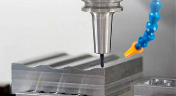
Table: realistic callouts by size class
Buyer question: what is a realistic flatness by size class? Size is only one variable. A compact thick block and a broad thin plate require different feasibility assessments even when the same numerical tolerance is requested. Use span, stiffness, removal pattern, and function to organize the discussion.
The table identifies the information needed to agree a limit. It intentionally avoids universal capability values because the plan provides no verified size-specific production data.
| Geometry class | Primary question | Drawing emphasis | Evidence before release |
|---|---|---|---|
| Compact, relatively stiff block | Which face controls assembly? | Defined surface extent and datum relationships | Suitable dimensional and form inspection |
| Broad mounting plate | What happens across the working span? | Whole face versus local contact zones | Coverage of the relevant area |
| Thin or heavily pocketed plate | How does release change the shape? | Free or specified restrained state | Inspection after release and relevant finishing |
| Separated mounting pads | Which pads establish the interface? | Explicit relationship between contact regions | Method matching the functional support |
Ask the supplier which requested limit drives extra work. Relax it only after checking that the assembly requirement still holds.
Inspection plans
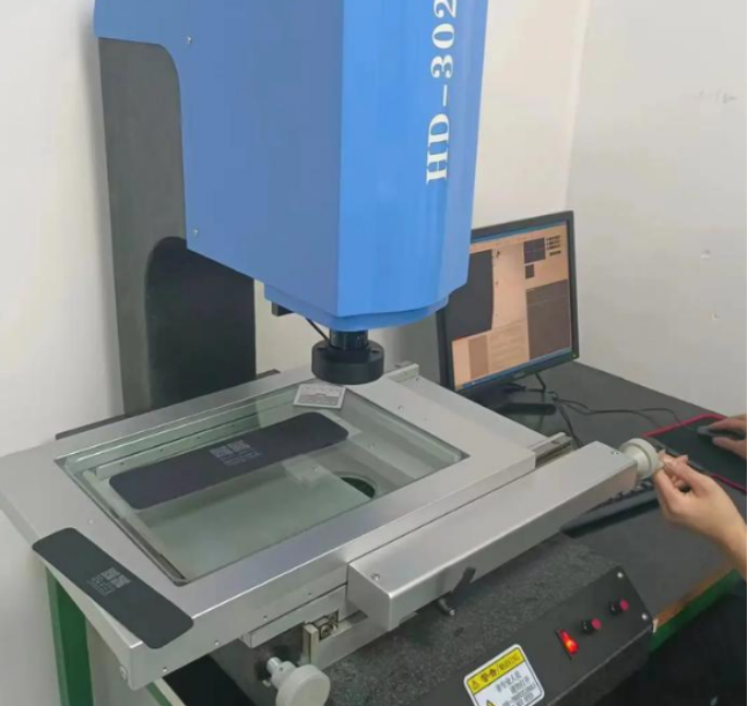
Buyer question: how will the supplier prove the surface meets the requirement? Agree the support, temperature, sampling pattern, evaluation method, and stage of manufacture. A few corner readings may miss a central high region or local distortion near a pocket.
NIST’s dimensional-metrology FAQ identifies 20 °C as the standard reference temperature. Temperature differences and gradients should be considered when the acceptance band is narrow. The report needs enough setup information to make comparisons meaningful rather than just listing a final number.
Distinguish surface texture from larger-scale form. Mitutoyo’s surface-roughness resource addresses the texture measurement topic. A favorable roughness reading does not prove flatness, and a flatness result does not establish the required texture. Include both where function demands them, with measurement conditions appropriate to each. Inspect after any operation that can alter the accepted surface condition.
FAQ
These questions address specification details that should be settled before sample approval.
Can a restrained plate be accepted against a free-state requirement?
Not unless the governing specification permits that restraint. A fixture can change the shape being measured and hide the released condition. Define the support and any allowed clamping before inspection, then report those conditions with the result. If the assembly genuinely requires a restrained state, communicate it through the controlled acceptance method rather than an informal shop practice.
Does a smoother face always provide a better mounting interface?
No. Texture and overall form influence different aspects of contact. A smooth surface can still bow or contain a high region that prevents stable seating. Specify the requirements needed for the mating function and evaluate them separately. Additional polishing or another finish should be reviewed for its effect on the final geometry and required surface state.
Should the entire plate receive the tightest local requirement?
Only if the function requires it. Some assemblies depend on defined mounting pads or a limited contact area, while others need the whole face controlled. Identify the actual interface and the relationship between its regions. A local requirement must not be used to ignore a whole-face function, but a whole-face callout should not be added without a reason.
Related process selection notes
Buyer question: does the requirement force an additional finishing process? That depends on the material, geometry, surface requirement, and proposed milling route. Ask the supplier to explain whether its process can meet the final specification and which operations or fixtures are included.
A precision machining review should distinguish a genuine process need from an unnecessarily restrictive callout. A smaller functional contact zone, a better datum choice, or an explicit restrained-state requirement may communicate the design more accurately. These are engineering changes, so approve them through the controlled drawing.
Keep appearance, texture, coating, and form requirements aligned. A secondary finish that improves cosmetics can change the final surface or acceptance sequence. Obtain the proposed plan before releasing the order, then make the approved sample and inspection method traceable to the same material and drawing revision.
Internal links and next steps
Prepare the RFQ with CAD, the controlled drawing, material condition, critical mounting interfaces, and the intended free or restrained state. Mark the surface extent and identify the processing stage at which acceptance applies. Include the required report and any functional assembly check.
Use the standards and tolerances reference as background while retaining the actual acceptance criteria in the project specification. Ask the supplier to return open assumptions, feasibility concerns, and the proposed measurement plan. Do not infer brand-specific flatness capability from a general machining description.
Send 6CProto the plate drawing and functional support conditions for a quote and DFM review. Resolve the relationship between thickness, flatness, and parallelism before accepting a price for a requirement the two teams interpret differently.