

Consider a hypothetical revision review for two pockets. One undercut remains reachable with a shaped cutter from a fixed direction; the other gains access only when the part or tool is reoriented. Calling both features five-axis work hides the difference. The useful comparison begins with the complete tool-and-holder path, then checks setup and inspection consequences.
Undercut geometries that force axes
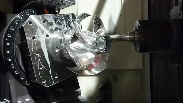
Choose 5-axis CNC milling for undercuts when reorientation provides usable tool access or controls critical relationships more effectively than a practical multi-setup route. Some undercuts remain reachable with specialized cutters using three-axis motion. Review cutter, holder, fixture, machine travel, and inspection access together before deciding that additional axes solve the feature.
Autodesk’s undercut-machining documentation shows both three-axis and five-axis approaches, including shaped tools for certain fixed-direction cuts. This supports an accessibility review rather than a blanket rule that every overhang requires simultaneous motion.
For the hypothetical pockets, identify the obstructing surface and the cutter shape needed to reach behind it. Check the holder and shank as well as the cutting edge. Reorientation cannot open a completely enclosed cavity or remove every physical obstruction. The 5-axis machining review should explain what access changes and what remains constrained.
Setup count vs cycle time trade-offs
Compare total work for accepted parts, including programming, fixtures, loading, alignment, cutting, and inspection. Fewer setups can reduce repeated handling, but the five-axis toolpath may take longer or need more development. A machine-axis count is not a complete cycle-time or price comparison.
For an illustrative one-part planning case, assume a three-setup route needs 20 minutes per setup and 90 minutes of cutting: 3 × 20 + 90 = 150 minutes. Assume the alternative needs one 35-minute setup and 100 minutes of cutting: 35 + 100 = 135 minutes. The hypothetical difference is 15 minutes before programming, fixtures, inspection, and other work. These inputs are not supplier production data or a quotation.
Recalculate for the actual batch. A reusable fixture can spread preparation over many parts, while an uncertain geometry can make repeated fixture revisions costly. Ask for the assumptions behind each route and identify which time estimates require trial evidence before using the comparison to release production.
Tolerances that still need fixtures
Additional axes do not eliminate workholding or datum decisions. The part still needs support without blocking the cut, and a finished feature must remain related to the functional references. A second operation may still be needed to remove a holding feature or reach the area occupied by the fixture.
ASME Y14.5 provides the language for the required geometric relationships. Keep those requirements independent of the preferred machine. If a relationship drives the choice of a common setup, identify it directly on the controlled drawing.
Renishaw’s machine-tool probing overview describes workpiece setup and in-process measurement applications. Probing can support the process, but it does not automatically replace a suitable final acceptance plan. Ask how a feature hidden during cutting will be inspected and whether the measurement remains valid after the part is released from its fixture.
Table: 3-axis multi-setup vs 5-axis
Return to the hypothetical pockets and compare the routes against the same requirements. The first may favor a simple fixed-direction operation; the second may justify reorientation to improve access. Neither result should be transferred to another part without reviewing its geometry and load path.
Autodesk’s 3+2 roughing documentation distinguishes fixed orientations from cutting with changing orientation. The buyer should ask which motion is proposed instead of assuming that a five-axis machine always uses simultaneous five-axis cutting.
| Question | Three-axis with setups or shaped tools | Positioned or simultaneous five-axis | Evidence needed |
|---|---|---|---|
| Can the cutter reach the feature? | May use shaped tools or another setup | May change the accessible direction | Complete tool and holder clearance review |
| Can the part be held? | Fixture may change between operations | Fixture must allow rotary access | Support and remaining holding feature |
| Are relationships maintained? | Setup transfer needs control | Common setup may help selected features | Datum and inspection plan |
| What drives total work? | Handling, fixtures, and specialized tooling | Programming, machine motion, and validation | Comparable accepted-part scope |
What to put on the RFQ
Provide the complete solid model, a marked view of the undercut, material and condition, critical dimensions, surface requirements, and quantity. Identify any feature whose geometry may change to improve access. If the appearance or function requires an uninterrupted surface, state that restriction before a split construction is considered.
Include the blank and proposed holding allowance if they are already selected. Ask the supplier to review the tool assembly, rotary envelope, fixture clearance, and final inspection route. A screenshot of the undercut alone can hide an adjacent wall or clamp that determines feasibility.
Sandvik Coromant’s tooling guidance discusses assembly length, stability, and access considerations. Use the actual tool configuration in the feasibility review rather than treating a long cutter as an unlimited access solution. Longer reach and smaller tool sections can change the practical cutting and finish conditions.
FAQ
These questions address specification details that should be settled before sample approval.
Does an undercut always require simultaneous five-axis motion?
No. Some undercuts can be reached with shaped tools using three-axis motion, another setup, or a fixed reorientation. Other geometries benefit from changing orientation during cutting. Review the actual cutter and holder clearance before choosing the route. The presence of an overhang identifies an access question, not an automatic machine requirement.
If the CAM simulation is clear, is the feature qualified?
It establishes evidence about the modeled path and collision conditions, within the completeness and accuracy of that model. It does not by itself prove material behavior, tool deflection, surface finish, or the final dimensional result. Confirm the relevant process and inspection evidence before production approval, especially where the fixture or tool assembly differs from the simulation.
Will fewer setups always produce a cheaper part?
No. The comparison also includes programming, tooling, machine time, fixtures, inspection, and the accepted output. A route with fewer setups can still require more overall work. Ask for comparable scope and the assumptions behind each proposal. Batch quantity and design stability can change which route is more economical without changing the nominal feature geometry.
Related process selection notes
In the hypothetical review, the decision would close only when each route has an accessible cut, a workable fixture, and an inspection method. The first pocket need not inherit a complex route merely because the second needs reorientation. Group operations where that improves the complete plan, not because every feature must share one process label.
Compare CNC milling options with explicit assumptions about setups and tooling. If neither route can reach the feature reliably, consider whether the design permits a geometry change, a split component, or another suitable manufacturing operation. Any design change needs approval against the function.
Keep the lesson limited to the evidence: an accessibility model can establish a candidate route, while representative manufacturing and inspection establish whether the part meets its requirements. Do not present a CAM path or an illustrative time calculation as an actual customer result or a demonstrated 6CProto capability.
Internal links and next steps
For the broader CNC machining inquiry, ask the quotation to identify the proposed axis strategy, number of setups, tool access concerns, holding features, and inspection assumptions. Separate optional geometry changes from the price for the current controlled design.
Approve the route when the supplier’s response explains the undercut rather than merely naming a machine. Confirm how any regripping affects the critical datums and what happens after the holding feature is removed. Include secondary finishing in the final inspection sequence where it can affect acceptance.
Send 6CProto the undercut model and critical relationships for a quote and DFM review. Request a comparison with the practical multi-setup alternative so that the selected process follows access, function, and complete program work.