

A sheet-metal part cracks at the bend, and the fabricator says the material is at fault while the engineer says the bend radius is too tight — both are partly right, and the missing variable is the grain direction. Rolled sheet metal has a grain structure from the rolling process, and bending behaves differently depending on how the bend line sits relative to that grain. A bend line parallel to the rolling direction is more prone to cracking at a tight radius, while a bend line perpendicular to the rolling direction is usually the safer orientation. A bend that works in one orientation can crack in another, and the drawing that does not control the grain direction leaves the cracking risk to the shop’s nesting choice.
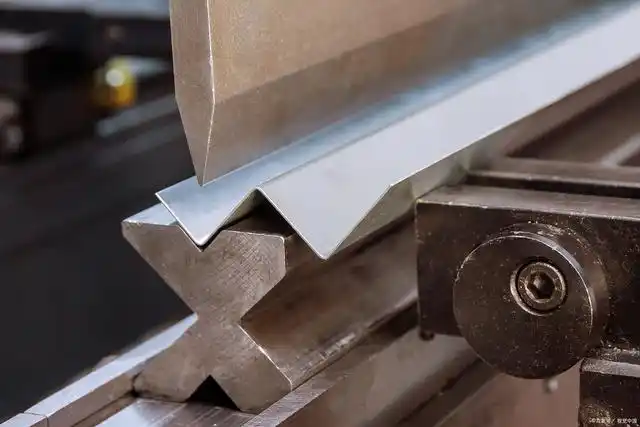
What grain direction means in rolled sheet
Rolled sheet metal is elongated in the rolling direction, and the material’s grains are stretched along that direction. The grain direction affects the mechanical behavior, and bending follows the pattern: a bend line that runs parallel to the rolling direction leaves the bend more prone to cracking at a tight radius, because the outer surface of the bend strains in the transverse direction where the material is less ductile; a bend line that runs perpendicular to the rolling direction is generally the safer orientation. The grain direction is a material property of the sheet, and the design and the nesting should account for it rather than treating the sheet as isotropic.
The grain effect varies by material: aluminum and some high-strength steels are more grain-sensitive than mild steel, and the bend behavior should be confirmed with the actual material and temper.
Bending across vs with the grain: crack risk
The crack risk is highest when the bend line runs parallel to the rolling direction, because the outer surface of the bend strains in the transverse direction where the material is less ductile and cracks can follow the grain. A bend line perpendicular to the rolling direction places the outer-fiber strain along the more ductile rolling direction and is generally safer at the same radius. The practical rule is to orient critical bend lines perpendicular to the rolling direction where the radius is tight or the material is grain-sensitive, and to avoid tight bends with the bend line parallel to the rolling direction. The drawing and the nesting should control the orientation for the critical bends, because the shop’s default nesting may place a bend parallel to the rolling direction without knowing the part’s requirement.
The crack risk also depends on the edge condition: a burred or sheared edge at the bend line can start a crack that the grain direction alone would not cause.
Minimum bend radius by material and temper
The minimum bend radius is set by the material, the temper, and the grain direction. Soft, annealed materials bend to tighter radii; hard tempers and high-strength grades need larger radii; and the radius may need to be increased when the bend line runs parallel to the rolling direction. The material supplier’s bend data provides the minimum radius for the grade and the temper, and the design should use it with the grain orientation in view. A radius that is marginal in the safer perpendicular orientation can fail when the bend line runs parallel to the rolling direction, so the drawing should state the radius and the orientation together when the material is grain-sensitive.
The bend radius is also affected by the thickness: thinner sheet bends to tighter radii relative to its thickness, and the minimum radius is often expressed as a multiple of the thickness.
Design workarounds: edge relief, bend orientation, and material change
When a tight bend parallel to the rolling direction cannot be avoided, the design workarounds are available. Add relief features at the bend ends so the stress does not concentrate at the edge; increase the bend radius where the design allows; rotate the feature or the nesting so the critical bend line runs perpendicular to the rolling direction; or change the material to a more formable temper. The workaround should be chosen by the cost and the design freedom: a relief is cheap, a radius change may affect the assembly, an orientation change may affect the nesting yield, and a material change affects the whole part. The review should start with the cheapest workaround and escalate only as the geometry requires. A bend that is designed around the grain is a bend that forms reliably.
The workaround should be verified on a sample, because the material lot and the edge condition affect the result more than the data sheet predicts.
Inspecting cracks and micro-fractures at the bend line
The inspection after bending should look beyond the visible crack. Micro-fractures at the bend line — small tears that do not break the surface — can weaken the part and grow in service, especially under fatigue or corrosion. The inspection method depends on the part: a visual check catches the gross cracks, a dye-penetrant or a bend test catches the micro-fractures, and a fatigue or corrosion test verifies the bend’s service behavior. The drawing should state the inspection for the critical bends, and the first-article review should confirm the bend is sound before the production run. A bend that looks clean on the surface can still carry the micro-fracture that fails later, and the inspection is what finds it.
The inspection should be repeated on a schedule, because the material lot and the tooling condition can change the bend behavior. The grain direction, the radius, and the inspection together make the bend a controlled feature.
Communicating the grain requirement to the shop
The grain requirement travels to the shop through the drawing and the nesting instructions. The bend note should state the material, the required bend orientation relative to the rolling direction, and the bend radius, so the shop’s nesting software places the critical bend lines perpendicular to the rolling direction where possible. The shop should confirm the sheet’s grain direction with the supplier, because the rolling direction is set by the sheet, and the nesting must know it to orient the part. A drawing that states the grain requirement turns the shop’s nesting decision from a guess into a controlled input; one that is silent leaves the bend orientation to the nesting algorithm, and the algorithm does not know which bends are critical.
The communication should also cover the material lot and the incoming check. A new sheet lot with a different grain or temper can change the bend behavior, and the incoming inspection should confirm the material against the specification before the parts are cut. The first-article bend test verifies the orientation and the radius on the production material, and the production inspection checks the bends at the interval that catches the drift. When the grain requirement is on the drawing and the material is confirmed, the bend is a controlled feature — and the sheet-metal part forms cleanly because the orientation was designed, not assumed.
The grain and bend review should also consider the part’s forming sequence and the tooling. A part with multiple bends must be nested so each critical bend line runs perpendicular to the rolling direction where possible, and the forming sequence should bend the critical features before the sheet work-hardens from the earlier bends. The tooling — the punch radius and the die — sets the actual bend radius, and the drawing radius should match the tooling that the shop will use, because a radius drawn tighter than the tooling produces either a tooling change or a cracked bend. The edge condition at the bend line is part of the forming design: the cut edges that fall at the bend should be clean, and the burr should be oriented away from the tension side of the bend. The forming review that covers the nesting, the sequence, and the tooling is the review that produces the bend the drawing promises, because the grain direction is only one of the variables that the forming process controls.
Record the bend validation with the part, including the material lot and the orientation, so the next order starts from the proven specification. The record turns the grain and the radius from a one-time fix into a controlled feature.
Confirm the bend test with the shop before release: the first article should be bent and inspected at the critical radius, and the result recorded with the material lot. The test is the final proof that the grain orientation, the radius, and the tooling produce a sound bend.
When the drawing carries the grain and the radius, the bend is a controlled feature; when it does not, the crack is a surprise. The orientation note is the difference.
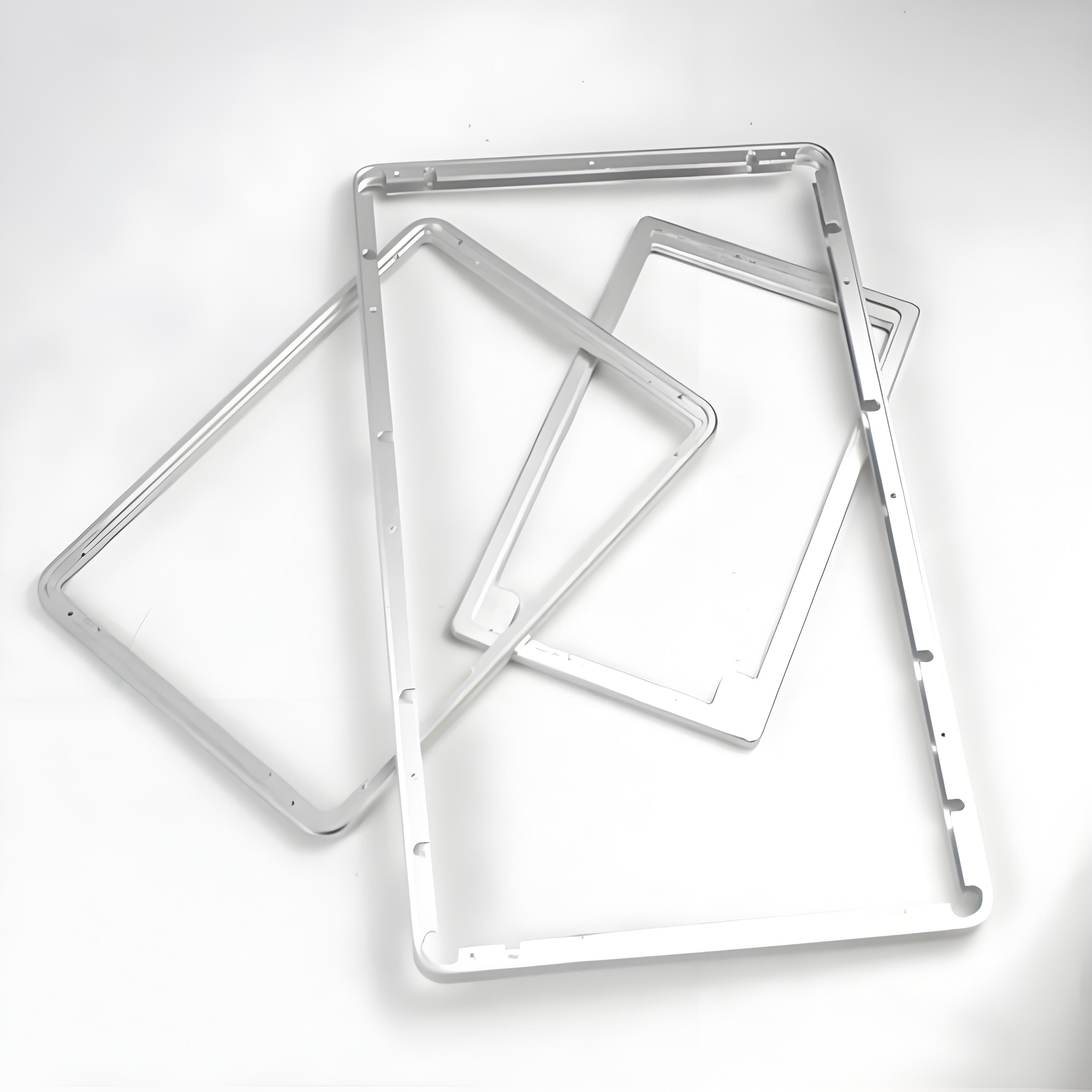
If you are designing sheet-metal parts with tight bends and want the grain orientation, the radius, and the inspection reviewed, the 6CProto sheet metal team can work from your material and geometry to the final bend specification.