

What Dimensional Tolerance Control Is and Why It Matters
Dimensional tolerance control is the systematic management of allowable variation in part dimensions to ensure function, interchangeability, and manufacturability. It spans design intent, process capability, inspection methods, and supplier qualification. The purpose is to keep the variation of every critical dimension inside the range that preserves function without inflating cost: a bearing bore may need 0.01 mm of control while a non-critical outer profile accepts 0.2 mm. Over-specifying tolerances on non-critical features drives up machining time, tooling cost, and inspection burden; under-specifying on critical features risks scrap, assembly downtime, and field failures. Tolerance control is what lets parts interchange across batches and suppliers, makes assembly predictable without selective fitting, and communicates the same requirement to design, manufacturing, and quality.
Standard Tolerance Systems: ISO 2768 and GD&T
Standard systems provide a common language. ISO 2768 defines general tolerance classes, f, m, c, and v, for unspecified dimensions, with f yielding tighter limits for metals and m often used for plastics, so a title-block line such as “General Tolerances ISO 2768-m” sets a baseline without dimensioning every feature. GD&T, typically per ASME Y14.5 or ISO 1101, controls geometric relationships rather than sizes alone: flatness, perpendicularity, position, concentricity, and runout, tied to datums. The two are used together: ISO 2768 for general dimensions and GD&T for the interfaces that carry function, sealing surfaces, bolt patterns, and alignment features. The result is a drawing that stays readable while controlling what matters.
Process Capability: What Each Process Can Pragmatically Hold
| Process | Typical critical-feature tolerance | Best for | Key constraint |
|---|---|---|---|
| CNC machining | 0.025–0.05 mm on stable features | Prototypes, tooling, low-medium volume | Setup count, material behavior |
| Precision injection molding | 0.05–0.10 mm critical, 0.10–0.30 typical | High-volume polymer parts | Shrinkage, warpage, tool wear |
| High-resolution 3D printing | 0.10–0.30 mm | Form/fit prototypes, complex geometry | Orientation and surface variance |
| Sheet metal forming | 0.1–0.5 mm for bends and cuts | Enclosures, brackets | Springback, tooling, bend accuracy |
CNC machining offers the tightest practical tolerances, especially 5-axis milling and precision turning on small, stable features, which is why it carries prototypes and tooling. Injection molding holds tight molded features but must account for resin shrinkage, warpage, and tool wear, and the mold tool itself is machined to support the part-level tolerance. Printed parts are excellent for form and fit but deliver wider variation by orientation. Sheet metal is set by bending accuracy and springback. The process should be selected to match the functional need and the volume, not the tightest number on the data sheet; the material selection and tolerance guidance pages frame the realistic window for each route.
Design Practices That Reduce Tolerance Risk
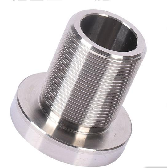
The design choices that reduce risk are the familiar ones, applied deliberately. Keep critical dimensions referenced to stable datums so manufacturing and inspection share the same reference. Separate the features that need tight control from the ones that do not, and avoid blanket tight tolerances that over-inflate cost. Design for the process capability, letting the expected shrink, springback, or layer behavior inform the nominal geometry. Use common sizes and standards where function allows, and remember that a hole position is often more important than a hole size in an assembly. The CNC tolerance guide turns these rules into the numbers that belong on the drawing.
Validating Tolerances at the Prototype Stage
The prototype is where tolerance strategy is tested before tooling. Measure the critical features against the drawing, confirm the datum scheme works for inspection, and check that the assembly still fits with the process variation. A prototype that passes with one process may fail with another, because the variation differs, so the validation should use the production intent process when the tolerance is functional. The inspection framework describes how the measurement program and datum alignment are set, and first-article verification at the production process confirms the strategy before volume.
Where Tolerance Failures Actually Occur
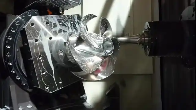
Assembly tolerance failures usually live in the relationships, not the individual sizes. A hole diameter can be perfect while the distance between holes is off; a shaft can be round while its shoulder is not square; a datum that differs between machining and inspection makes the same part pass one check and fail another. The failures cluster around datum misalignment, tolerance stack-up across multiple parts, and features whose relationship to function is not controlled. The fix is to trace the assembly requirement back to the features and set the GD&T and datum scheme to control the relationship, and to review the stack-up early in design. Tolerance stack and datum analysis are where engineering judgment replaces guesswork, and the complex parts guide covers the same discipline for difficult geometry.
Who Sets the Tolerances and Why It Cannot Be One Person
Setting tolerances is a joint decision: design owns the function, manufacturing owns what the process can hold, and quality owns whether the inspection can prove it. A tolerance that design wants and the process cannot hold fails in production; one the process can hold but quality cannot measure fails at inspection. The review should bring all three together, with the supplier providing the process capability and the inspection plan while the designer names the functional requirements. When the conversation is grounded in the actual drawing and material, the result is a tolerance set that is achievable, measurable, and tied to function. Standards such as NIST measurement practice provide the reference for how the results are verified and reported.
When Tighter Is Not the Answer
Switching to a tighter process does not automatically fix a tolerance problem. If the drawing is wrong, the datum is ambiguous, or the assembly stack is the issue, a tighter machine produces the same failure more expensively. The correct sequence is to fix the source first, the datum, the reference, the stack-up, then select the process capable of the requirement, and confirm the inspection can prove it. Only after those are settled does a process change make sense. This is the difference between tightening the tolerance and controlling it, and the tolerance standards page frames the practical limits for each route.
Tolerance Stack-Up: The Hidden Assembly Risk
Every dimension in an assembly contributes to the final fit, and tolerance stack-up is the arithmetic of that accumulation. Two parts that each meet their individual tolerances can still assemble poorly if the stack of their variations exceeds the allowed gap or clearance at the interface. The analysis is straightforward: the worst-case sum of the contributing tolerances, or a statistical estimate when variation is understood, shows whether the assembly will fit, bind, or rattle. The fix is rarely to tighten everything; it is to identify the worst contributors, control the relationship features with GD&T and datums, and adjust the nominal geometry to absorb the stack.
The stack analysis belongs in the design review before the first prototype, because a fit that cannot close on paper will not close in metal. Prototypes then confirm the prediction, and the production inspection should measure the contributions that drive the stack rather than every feature on the drawing. Coordinating the dimensions and tolerance plan with the actual machining, molding, and fabrication capabilities, with the tolerance standards as the reference, is what turns a stack-up analysis into a manufacturable design.
Tolerance Optimization and Cost
Tolerance is a cost driver in a predictable way: each step tighter increases machining time, inspection effort, and scrap exposure, often by more than the geometric improvement. The optimization is to spend the tolerance budget where the function needs it and relax it where it does not. A bore that locates a bearing gets the tight control and the inspection; a chamfer that only prevents edge damage accepts a general tolerance. The drawing that separates these avoids the cost of over-specification and the risk of under-specification at the same time.
The supplier engagement is where the optimization is validated. A DFM review that names the process capability for each critical feature, the realistic window, and the alternatives, lets the designer set tolerances with evidence rather than habit. The quote and the plan should follow the same structure, with the critical features priced and inspected individually, as described in the DFM checklist, so the tolerance plan and the cost plan are one document.
Tolerance control is ultimately a management discipline: the drawing, the process, the inspection, and the supplier all have to agree on the same variation, or the part will not mean what the drawing says. That alignment, more than any single number, is what separates a controlled part from a tolerated one.
FAQs
What is the difference between ISO 2768 and GD&T?
ISO 2768 sets general size tolerances for unspecified dimensions, while GD&T controls geometric relationships tied to datums. Most production drawings use both, ISO 2768 for general dimensions and GD&T for the critical interfaces.
Which process holds the tightest tolerances?
CNC machining, especially 5-axis milling and precision turning, holds the tightest practical tolerances on stable metal features. Injection molding, 3D printing, and sheet metal each have wider practical windows that must be respected.
Why do assemblies fail even when each part is in tolerance?
Usually because the tolerance relationships, datum alignment, stack-up across parts, or the control of a relationship feature, are not specified. The fix is a GD&T and datum review that ties the assembly requirement back to the controlled features.