

A threaded part passes its go/no-go gauge at the supplier and jams on the mating screw at assembly. The gauge said the pitch diameter was in range, and the screw still will not fit — because the thread is tilted, or the coating closed the fit after gaging, or the gauge was checking the wrong length of thread. Thread inspection is more than running a go gauge: it is verifying size, pitch, depth, position, and coating condition, and writing a report that says what was actually measured. The parts that assemble without arguments are the ones whose threads were inspected the way they will be used.
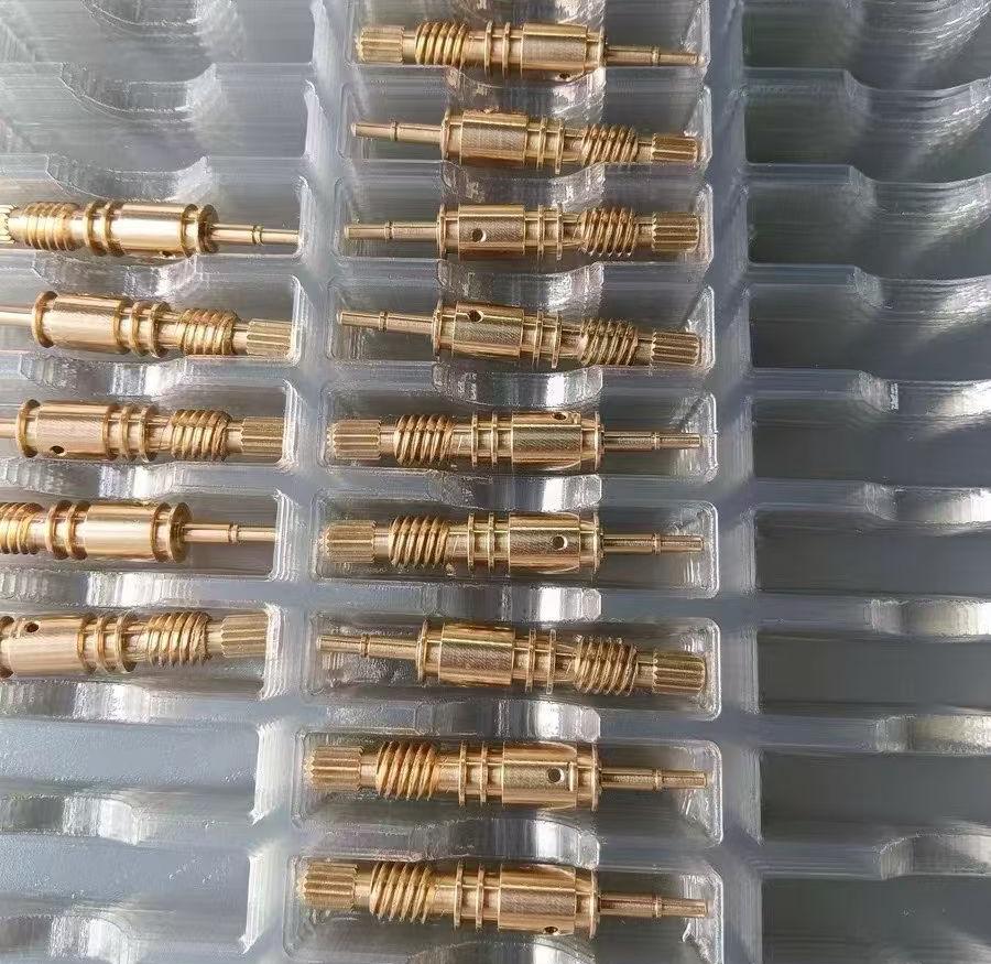
What makes a thread pass: size, pitch, and pitch diameter
A threaded feature is defined by its major and minor diameters, its pitch, and its pitch diameter — the imaginary cylinder where the thread thickness equals the space between threads. The pitch diameter carries most of the fit, which is why thread gages focus on it. A thread can be within nominal size and still fail if the pitch is wrong, the thread is tapered, or the pitch diameter drifts along the length. The inspection plan should verify the features the function needs: the size and pitch for any thread, the pitch diameter for fit, and the depth and position for threaded holes that receive a specific screw.
The drawing and the inspection must use the same standard — ISO 965 for metric, ASME B1.1 for Unified, ASME B1.20.1 for NPT — because the class limits and the gage design follow the standard.
Go/no-go gaging and what it can miss
Go/no-go gages are the fast, practical check for most threads: the go member must assemble fully, and the no-go member must not. The system verifies the pitch diameter and the fit class quickly and is the right tool for production inspection. What it misses is the information a functional thread needs: depth in a blind hole, thread position relative to a face, runout, and the condition of the thread at the bottom. A thread can pass its gage and still be too shallow, tilted, or damaged where the gage cannot reach. The drawing should separate the gage check from the depth and position checks, because the gage alone answers only part of the requirement.
Gage condition is part of the method: worn or dirty gages produce false results, and gages should be calibrated and verified on a schedule. The inspection record should name the gage class and its calibration date, because a result from an uncalibrated gage is not evidence.
Measuring pitch diameter with wires and CMM
When a thread needs a numeric pitch-diameter value — for a first article, a dispute, or a coating-allowance calculation — the practical methods are wire measurement and coordinate measurement. The three-wire method measures the pitch diameter precisely on external threads and is the classic referee method; internal threads are harder, often measured with thread plugs, specialized indicators, or CMM probing with the right algorithm. Each method has its own uncertainty, and the report should name the method so two results can be compared honestly. A CMM thread measurement is only as good as the probing strategy and the algorithm, so confirm the method with the inspection engineer when the number matters.
| Method | Best for | Notes |
|---|---|---|
| Go/no-go gage | Production pass/fail | Fast; does not verify depth or position |
| Three-wire | External pitch diameter, referee | Precise when done to the standard |
| Thread plug / indicator | Internal thread fit | Verifies fit, not a numeric value alone |
| CMM probing | Position, runout, geometry | Method and algorithm must be stated |
The table maps the method to the question; the report should say which method answered which question.
Coating allowances and plating effects on gaging
Plating and anodizing change thread size, and the inspection must match the drawing’s measurement basis. If the drawing says the thread is measured after coating, the gage check happens on the coated thread; if it is measured before coating with an allowance, the gage result applies to the pre-coat size and the coated fit is verified separately. The common failure is gaging before coating and shipping after coating without rechecking, which lets a plated thread close in past the fit. State the basis on the drawing, plan the allowance before tapping or cutting, and check the fit with the actual mating part when the coating is thick enough to matter.
Coating thickness on threads is not uniform, so a single thickness reading on a flat face does not prove the thread fit. The functional check is the assembled fit or a post-coat gage, and that is the record that matters for the assembly.
What a thread inspection report should show
A useful thread report identifies the feature, the standard, the class, and the measurement basis, then reports the results: the gage result or the measured pitch diameter, the thread depth, the position or runout where required, and the coating state. It names the instruments and their calibration dates, and it references the drawing revision. A report that says only “thread OK” has verified nothing the gage did not already claim. The report should let a second inspector repeat the measurement and reach the same result — that repeatability is what makes the report evidence rather than opinion.
The threading guide on this site explains how threads are manufactured; this page covers how they are verified. When a thread fails, the report should separate the failure mode — size, depth, position, or coating — so the fix targets the actual cause.
A dispute example shows the report in action. A threaded part is rejected at the buyer’s incoming inspection because the mating screw will not start cleanly, while the supplier’s go/no-go record shows the thread passed. The two sides compare records: the supplier gaged the thread before plating, and the buyer is assembling the plated part. The drawing states the thread class and the plating, but it does not state whether the fit is verified before or after coating. The referee measurement is done on the plated thread with a calibrated plug gage, and it fails — the coating closed the pitch diameter. The fix is a pre-plate allowance or a post-plate chase, and the drawing note is updated to state the measurement basis. The same dispute could have been avoided by a report that showed the coating state and the measurement basis on the first article. The lesson applies beyond plating: a thread report that names the standard, the class, the gage, the calibration, the coating state, and the drawing revision is a document that two parties can agree on; a report that says “thread OK” is a claim that depends on whoever is reading it. When the report is repeatable, the thread inspection stops being an argument and becomes a record — and the record is what lets the next order start with the allowance already planned.
Build the thread inspection plan from the drawing: the standard and class, the features the assembly needs (fit, depth, position, coating state), the gage or measurement method for each, and the calibration records. State the measurement basis before or after coating, and report the results with the instrument and the revision. A plan written this way is repeatable by any inspector — and repeatability is what makes the inspection a record instead of a claim.
Frequently asked questions
Why does a thread pass the supplier’s gage and fail at our assembly?
Usually because the two checks measure different things or different conditions: the supplier gaged the thread before coating and the assembly uses the coated thread, or the supplier checked size while the assembly needs position and depth. Compare the measurement basis and the feature set, and align the incoming check with the drawing’s functional requirements.
Can a thread be inspected without a gage?
Yes, with wires, optical measurement, or CMM probing, but each method must be validated against the standard and the part geometry. Gages are fast and traceable for production; numeric methods are useful for first articles, disputes, and features that gages cannot reach. Choose the method by the question and document it in the report.
How often should thread gages be calibrated?
On a schedule defined by use and the quality system — commonly annually with more frequent verification if the gage is heavily used or dropped. A gage that fails calibration invalidates the results taken since the last valid check, which is why the record should tie each inspection to the gage and its calibration date.
The thread inspection in one paragraph
Inspect threads the way they will be used: gage the fit, verify depth and position where the assembly needs them, measure the pitch diameter numerically when the number matters, and check the coated condition against the drawing’s basis. Write the report so a second inspector can repeat it. The threaded parts that assemble without dispute are the ones whose inspection matched the drawing, the standard, and the coating — not just the go gauge.
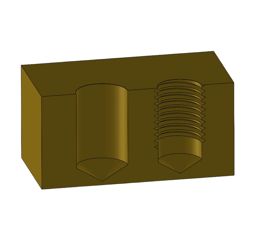
If you are defining thread inspection for a machined part or resolving a thread-fit dispute, the 6CProto quality team can review the standard, the gage class, and the measurement basis with you before the parts ship.