

The first parts off the line showed two defects that came from one cause. The blind holes in the brass were barely plated, and the mouths of those same holes had turned a heavy yellow. Both are current-distribution problems, and both were solved by changing where the current came from rather than by changing the chemistry of the bath.
Last updated:
Why Blind Holes Plate Unevenly
Electroplating depends on two things arriving at the same place at the same time: metal ions in solution, and current. In an open recess, neither arrives easily. The solution inside a blind hole exchanges slowly with the bulk tank, so the ions are used up faster than they are replaced, and the current density falls off with depth because the hole is a recess in an electric field. The result is a thin, patchy or missing deposit at the bottom, which is exactly what a plated brass part cannot afford: the hole is usually there for a fastener, a pin or a light path.
The second defect has the opposite cause. The rim of a hole is a high-current-density area, because current concentrates on edges and protrusions. Where the local current density runs too high, the deposit burns: it goes dull, dark or strongly coloured, and in a bright nickel-then-chrome sequence it shows as a yellow halo around the opening. The two defects sitting side by side on the same part is the signature of a geometry that starves the recess and overfeeds the edge.
The Fix: Auxiliary Electrodes
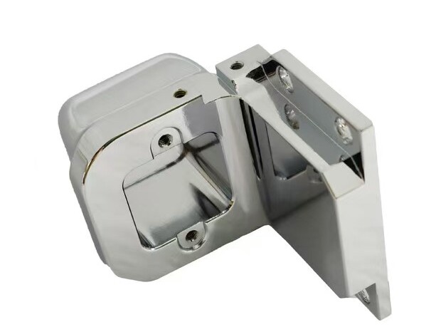
The job came from a client who needed brass parts plated with nickel and then chromium, for corrosion resistance and for appearance, with the plating applied over an initial nickel layer before the chromium. The first attempts failed on exactly the two mechanisms above: the solution could not reach the inside of the blind holes, so the plating was uneven or absent, and the hole entrances discoloured badly enough to raise questions about both the look and the durability of the coating.
The solution was to place auxiliary electrodes near the blind holes and near the hole entrances. Inside the recess, an auxiliary electrode changes the field so that current reaches the surfaces the main anode cannot see, and it encourages the solution to move into the hole rather than stagnating in it. At the rim, the same electrode redistributes the current so the entrance is no longer the highest-current-density point on the part, which is what stops the abnormal deposit that produced the yellowing. Placing them is not a standard fixture: the shape, size and position of each electrode were designed around the geometry of the specific brass part, and the plating parameters — voltage, current density and plating time — were controlled precisely through the run rather than set once and left.
The outcome was a smooth, continuous, evenly distributed nickel and chromium layer inside the blind holes, at the standard the client had specified, with the discolouration at the entrances gone and a uniform, shiny surface across the parts. The client accepted the batch, and the case became the reference for later work on recessed features.
Reading the Defects
Most plating faults on a machined part can be read the same way, from where they appear rather than from what the bath analysis says:
| What you see | What causes it | The design or process response |
|---|---|---|
| Blind holes unplated or patchy | Poor solution exchange and low current density inside the recess | Auxiliary electrodes, agitation, or a drainage path designed into the part |
| Discoloured or burnt rim around a hole | Current concentrating at the edge, so the local deposit burns | Redistribute or shield the current, soften the edge geometry, control the current density |
| Heavier deposit on sharp edges | Edge effect: current concentrates on protrusions | Break edges deliberately on the drawing instead of leaving them sharp |
| Threads that will not accept a mating part | Internal threads close in, external threads grow beyond class | Allow for the coating, pre-plate undersize, mask, or chase the thread after plating |
| Rack marks on a cosmetic face | The contact area is also a finish-free area | Define where contact is allowed, or mask the face |
Those responses are the ones the shop sets out in its guide to designing parts for plating and anodising, and they belong on the drawing rather than in a conversation after the first batch fails.
Thickness, Adhesion and What the Records Should Show
Plating is specified in micrometres or microinches, and the practical range for functional work runs from roughly 2.5 µm to 500 µm, with decorative coatings sitting at the thin end. The number that matters is the one the function needs: a cosmetic nickel-chromium finish and a wear surface on a sliding contact are not specified with the same target, and specifying by habit rather than by function is how a part ends up either under-protected or unnecessarily expensive.
There are boundary conditions that change the process rather than the appearance. High-strength steels above roughly 40 HRC carry a risk of hydrogen embrittlement and need a stress-relief bake after plating, typically within hours at 190–220 °C, and aluminium needs a zincate pre-treatment before it will take a durable deposit at all. Neither applies to a brass part, but both belong in the conversation before a plating job is quoted on geometry alone. The thickness bands, the bake figures and the failure modes are documented in the shop’s guide to electroplating services.
Because the defects only appear after the parts have been processed, the records carry the proof. Ask for a coating thickness measurement on the finished part, an adhesion test result, a corrosion test result on the actual coating combination where the service environment demands one, and an agreed colour and appearance master sample for anything visible. Where a test has not been run, the honest answer is that it is available on request — never a result invented after the fact.
Choosing the Coating
Nickel followed by chromium was right for this part because the requirement was corrosion resistance plus appearance. The same decision made for a different requirement lands somewhere else, and the trade-off is short enough to hold in one table:
| Coating | Primary function | Typical applications | Main limitation |
|---|---|---|---|
| Zinc | Corrosion protection | Fasteners, brackets, hardware | Wears quickly and needs passivation |
| Nickel | Corrosion, wear, restoration | Worn parts, undercoats | Thickness control on edges |
| Hard chrome | Wear and friction | Hydraulic rods, tooling | Hydrogen embrittlement risk on hardened steel |
| Gold | Electrical contact | Connectors, semiconductors | Material cost |
| Silver | Conductivity | RF parts, high-power switches | Tarnishes |
The table is the one in the shop’s electroplating guide, and it holds the same warning that this page does: the edge is where plating fails first, so the thickness that is easy to measure on a flat face is not the thickness that matters on the feature the part was designed around.
FAQ
Why do blind holes not plate evenly?
Because a recess starves both inputs at once. The solution inside the hole exchanges slowly with the tank, so the metal ions are consumed faster than they are replenished, and the current density falls with depth because the hole sits in a recess in the electric field. Auxiliary electrodes placed near the hole restore both.
What causes yellow discolouration around a plated hole?
Current concentrates at the rim of a hole, so the local current density runs higher than on the flat surface and the deposit burns, which shows as a dull, dark or strongly coloured halo around the opening. Redistributing the current with a shielding arrangement or a nearby auxiliary electrode, and softening the edge geometry, removes the cause.
How thick should nickel and chrome plating be?
Specify by function, not by habit. Functional plating commonly runs from about 2.5 µm to 500 µm, with decorative coatings at the thin end, and a cosmetic nickel-chromium finish does not share a target with a wear surface. State the number and the measurement method on the drawing, and remember that the edge is where the deposit is thickest and where the part fails first.
Which coating should I choose for a brass part: zinc, nickel or chrome?
Zinc is a corrosion coating for steel hardware and wears quickly without passivation. Nickel covers corrosion, wear and restoration work and is often used as an undercoat. Hard chrome is chosen for wear and friction, but carries a hydrogen-embrittlement risk on hardened steel. For brass where appearance and corrosion resistance both matter, a nickel layer under chromium is the usual combination.
What proof of plating quality can I ask for?
A coating thickness measurement taken on the finished part, an adhesion test result, a corrosion test result on the actual coating combination where the environment demands one, and an agreed colour and appearance master sample for visible parts. If a test has not been run, the correct answer is that it is available on request.
Latest Post
Vacuum Casting VS Injection Molding: How to Choose the Right Manufacturing Process from Prototype to Production

History of CNC Machining: The Origins and Development of Computer Numerical Control
The Ultimate Guide to Injection Molding: Process, Types, Advantages & Applications

How to Choose the Right 3D Printing Process: An Analysis of Pros and Cons

What is CNC Machining?A Complete Guide to Processes,Advantages,and Applications
Sheet Metal Enclosure Design: Corners, Sealing and Service Access
K Factor Sheet Metal Bending: Why the Same Model Gives Two Different Blanks
Custom Metal Fabricated Assemblies: Buying the Finished Item, Not the Parts
Laser Cut Prototypes: Flat Part Design and What the Cut Edge Gives You