

The prototype is signed off, the tool is cut, and the first production parts do not assemble. In most cases the cause is not the tool: it is that nobody agreed which features were critical, how they would be measured, or what deviation would be acceptable at prototype stage. Welded and formed sheet metal parts move during processing, and a prototype inspection that records those movements is what makes the tooling decision safe. This guide covers which tolerances belong on a prototype drawing, how flatness and twist behave, what inspection is practical at prototype quantity, and how to document the result.
Which tolerances belong on a prototype drawing?
Only the ones that decide the outcome.
A prototype drawing should carry a general tolerance for cut features, a wider one for formed features, and explicit callouts only on the interfaces that must align with other components.
The reason is that prototype fabrication uses general processes rather than dedicated tooling, so every formed feature carries variation that has nothing to do with whether the design is correct. Applying production tolerances across the whole part creates rejections that consume time without improving the design decision.
A more useful structure separates the part into three groups. Cut geometry, such as profiles and holes produced by laser, is accurate and can carry a tighter general tolerance. Formed geometry, including bend angles and the position of features relative to a bend, needs a wider tolerance that reflects the process. And the interface features, the holes that bolt to another component or the flanges that meet another panel, carry explicit callouts agreed with the shop before the parts are made.
The framework for those classes, including general tolerances for linear and angular dimensions, is set out on 6CProto’s standards and tolerances page. Where a callout is genuinely critical, the drawing should also say how it will be measured, because a tolerance that cannot be inspected at prototype quantity is a note rather than a requirement.
How do flatness and twist behave in formed parts?
They are the hardest features to control.
A formed panel accumulates distortion from the bending process and from any welding, so flatness and twist should be specified only where they matter and measured on the features that matter.
Flatness in sheet metal is a function of the process. Bending introduces residual stress that can bow a panel; a small amount of cross-bow across the bend itself appears even in repeatable production, because the outer material stretches while the inner compresses. Welding adds a second effect: the local heating and cooling pulls the panel toward the weld, and a long weld along a panel edge can visibly bow the whole component.
Twist behaves similarly. A part that is not symmetric in its forming sequence tends to twist slightly, and the effect increases with panel size. On a prototype, that movement is often larger than on a production part, because the forming is done with general tooling rather than a dedicated die that controls the material flow.
The practical approach is to specify flatness on the surfaces that perform a function, such as a mounting face or a sealing surface, and to leave other panels with a general requirement. Where flatness is genuinely critical, the more reliable answer may be to machine that face after forming rather than to rely on a forming tolerance. The material behaviour behind that distortion, including how each alloy responds to forming and welding, is documented by bodies such as ASM International.
How should hole position, bend location and edge quality be judged?
Against the function, not against a blanket tolerance.
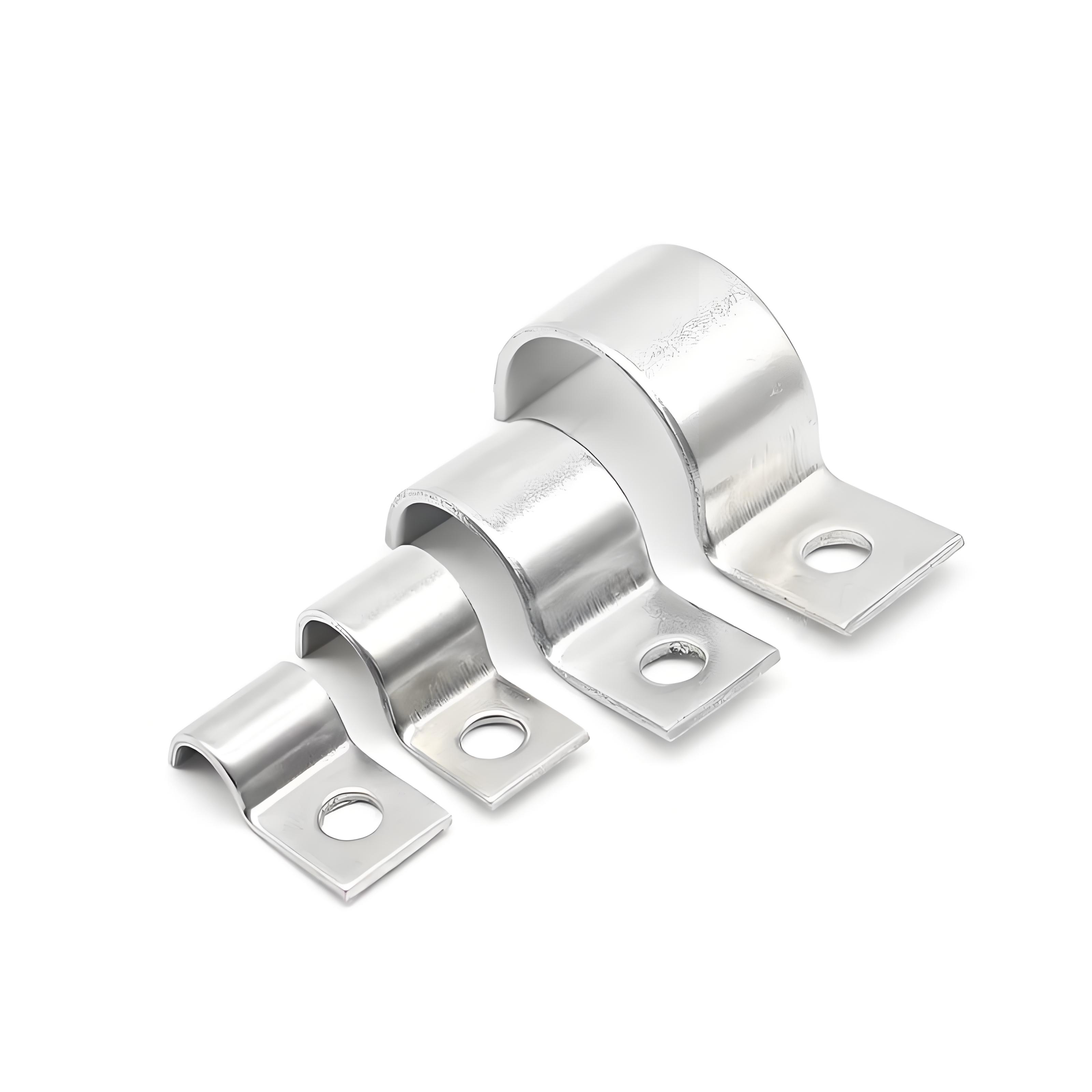
A hole that accepts a screw has different needs from a hole that locates a component, and a bend that creates a clearance has different needs from one that sets an aesthetic line.
Hole position should be judged by what the hole does. Mounting holes for a screw need enough clearance to account for tolerance stacking across the assembly, which is usually a generous requirement. Locating holes that set the position of a component, or pilot holes for self-clinching hardware, need tighter control because the hardware position defines the assembly. That distinction should be visible on the drawing rather than left to be inferred.
Bend location is measured from the features that the bend relates to, not from a datum that the process cannot hold. A bend that creates clearance between two panels is judged by that clearance. A bend that establishes an exterior corner is judged by the resulting geometry and by how it reads in the assembly, which is often a looser requirement than a dimensioned angle suggests.
Edge quality follows the process. Laser cutting leaves a clean edge with a small heat-affected zone, and burrs appear on the underside unless they are removed. On a prototype, deburring is usually specified for handling safety and for assembly, while a production part may need edge quality defined for a coating to adhere correctly.
Which inspection methods fit prototype quantities?
Measurement proportionate to the decision.
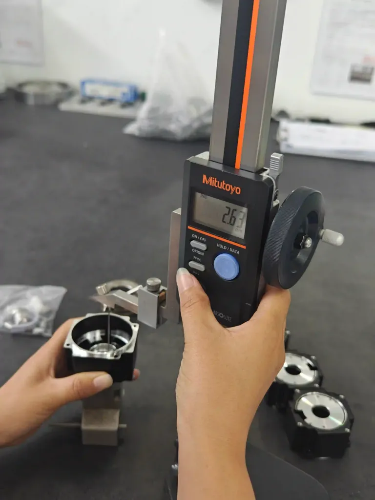
At prototype quantity, the useful inspection is dimensional measurement of the critical features with hand tools or a height gauge, plus a fit check.
Inspection at this scale does not need a coordinate measuring machine to be meaningful. Calipers and a height gauge measure hole positions, panel dimensions and flange lengths accurately enough to confirm a design. A surface plate with height gauge is the standard tool for checking flatness on a mounting face. And an assembly check, bolting the prototype to its mating parts, answers the question that matters most: does the design work.
Where the program has a metrology requirement that hand tools cannot satisfy, the time to establish that is during the design review, not after the prototype is made. Instrumented measurement adds cost and lead time, and it is justified where the feature is genuinely critical or where the customer’s quality system demands a record.
The measurement equipment available for those checks, including dimensional verification of formed and machined features, is described alongside the tolerance framework on the standards and tolerances page.
What does a first article inspection check without production tooling?
The design, not the tool.
A prototype first article confirms that the part matches the drawing within the tolerances agreed for general fabrication, and it establishes the measurement method that production parts will be judged against.
Four things belong in that check. Dimensional results on the interface features, recorded with the method used. A record of the material grade and thickness actually used, since a substitution changes the meaning of the results. The finishing steps applied, because coating thickness affects fits. And an assembly check that demonstrates the prototype works with the components it was designed to meet.
What it does not check is tool capability. A press-brake formed prototype and a stamped production part have different bend behaviour, so the prototype report establishes the design intent rather than the achievable production tolerance. That distinction matters when the same report is later used to judge production parts.
Where a program intends to move to tooling, the first article report becomes the baseline. Production parts are then compared against the same features and the same acceptance method, which makes the comparison meaningful rather than a fresh negotiation.
| Prototype question | What to measure | Method |
|---|---|---|
| Does the assembly close? | Interface holes and mating faces | Assemble with the mating components |
| Is the panel flat enough? | The functional face only | Surface plate and height gauge |
| Do bends land correctly? | Feature positions relative to each bend | Height gauge against a datum |
| Will hardware install? | Pilot hole size and wall around it | Install the specified hardware |
| Is the design suitable for tooling? | Bend radii, reliefs and flat pattern | Review against forming limits |
| Does the finish meet the brief? | Appearance and fits affected by coating | Compare with the reference sample |
How should deviations be recorded?
Openly, with the cause.
A deviation that is recorded and explained is useful information; the same deviation concealed is a risk that reappears at tooling stage.
Deviations at prototype stage usually fall into three categories. Process-driven deviations, such as a bend angle that sits slightly outside the general tolerance because of springback, are normal and may need no design change. Design-driven deviations, such as a relief that is too small to form cleanly, indicate that the drawing needs revision. And measurement-driven deviations, where the feature is within tolerance but the measurement method was ambiguous, indicate that the acceptance criteria need to be clearer.
Sorting deviations into those categories turns the prototype report into a decision document. It shows which issues must be fixed before tooling, which can be accepted as process variation, and which require an agreement about how the feature will be measured. That is more valuable than a pass or fail statement, and it is the reason prototype inspection should be discussed before the parts are made.
6CProto provides quality inspection reports on request and assigns a dedicated project manager to each order, so the reporting format and the acceptance method can be agreed with the quote rather than reconstructed after delivery. Where a formed part is subsequently coated, adhesion and surface preparation follow documented test methods such as ASTM D3359, and any chemical waste from a plating or coating step is handled under the framework published by the US Environmental Protection Agency.
What acceptance criteria should be agreed before release?
The features, the method and the fallback.
Before the prototype is released, agree which features will be measured, how, what result is acceptable, and what happens if a feature falls outside that range.
The features should be a short list, ideally the interfaces that decide whether the assembly works. The method should be specific enough that two people would reach the same result: measured with a caliper against a datum, or checked by assembling with the mating component. The acceptance range should reflect what the part must do rather than a generic tolerance class. And the fallback should be agreed in advance, so that a deviation leads to a decision rather than a delay.
That last item is the one most often missing. Prototype work involves processes that are being used to explore a design, and some variation is expected. Deciding in advance which deviations are acceptable and which trigger a design change removes the standoff that otherwise appears when a prototype arrives slightly outside a specification that was never discussed.
The design rules that reduce the likelihood of those deviations, from bend radius guidance to relief dimensions, are collected in the sheet metal fabrication design tips.
Documentation for the tooling decision
The purpose of prototype inspection is to make the next investment safe. That requires a short, clear record: the material and thickness used, the finishing steps applied, dimensional results on the features that carry the assembly, an assembly check, and a list of deviations with their causes. Together those items show whether the design is ready for tooling and what the production inspection plan should cover.
Two habits make the record useful. Agree the acceptance method before the parts are made, so the results mean the same thing to everyone who reads them. And keep the record with the design revision it belongs to, because a prototype report that cannot be matched to a drawing is of limited value later. The manufacturing guidance published by NIST MEP covers the quality practices that support that kind of documentation, and the coating and surface subject matter that often accompanies formed parts is covered by ASTM committee B08.
FAQ
What is the standard tolerance for sheet metal?
There is no single figure, because cut and formed features behave differently. Laser-cut profiles and holes hold tighter tolerances than formed features, and bend angles vary with material, radius and tooling. The practical approach is a general tolerance that matches the fabrication method, plus explicit callouts on the interfaces that must align. The general classes that apply are set out in the tolerance framework published by 6CProto.
What is a typical flatness tolerance for a formed panel?
It depends on the panel size, the material and whether the part is welded. Bending introduces some cross-bow across the bend, and welding adds local distortion that can bow a long edge noticeably. Rather than applying a blanket figure, specify flatness only on the faces that perform a function, such as a mounting or sealing face, and expect to confirm the achievable result on a prototype before committing to it.
Does material thickness tolerance affect the finished part?
It does, in two ways. Thickness variation changes the stiffness of the part, which matters where the design depends on rigidity. It also changes the flat pattern, because the bend allowance depends on thickness, so a panel at the top of the thickness range forms slightly differently from one at the bottom. Where a design sits close to a forming limit, the material specification and its thickness tolerance are worth stating explicitly.
Should a prototype be inspected before or after finishing?
Both, where the finish affects the measured outcome. Coating and plating add thickness, which changes fits and thread engagement, so measuring only before finishing misses the condition the part will be in service. Measuring only after finishing makes it harder to separate a forming deviation from a coating effect. The practical sequence is to check the critical features before finishing, apply the finish, then confirm the fits that the coating affects.
If a prototype has to justify a tooling decision, send the model with the interfaces that must align and ask for dimensional results on those features. 6CProto reviews sheet metal parts for manufacturability, provides inspection reports on request, and follows each order with a dedicated project manager so the acceptance method is agreed before the parts are made. Upload the file at the 6CProto quote page or send it to projects@6cproto.com.