

A hypothetical 0.10 mm of finishing stock can disappear entirely if polishing removes 0.10 mm from the same face. That simple allowance check matters when an acrylic surface must remain both clear and dimensionally controlled. PMMA machining for optical-clarity faces needs a defined viewing region, a controlled finishing route, and acceptance criteria that extend beyond a glossy photograph.
Optical faces vs structural ribs
Specify PMMA machining for optical faces by the functional aperture, material grade and stock form, surface geometry, finish route, protected interfaces, and measurable acceptance requirements. Separate transparent appearance from optical performance. Keep tool access, polishing allowance, stress, and compatible handling in the review, then validate the finished component under representative viewing or operating conditions.
Mark the region through which a user, camera, or light source actually operates. A mounting rib or decorative edge may need a different finish from that region. Identify whether stock surfaces can remain intact or whether machining must generate a new viewing face.
The PLEXIGLAS machining guide discusses machining and polishing routes for its acrylic products. Use appropriate stock-specific guidance and identify which surfaces must retain their geometry. A transparent edge demonstration does not prove the wavefront or image quality of a machined optical face.
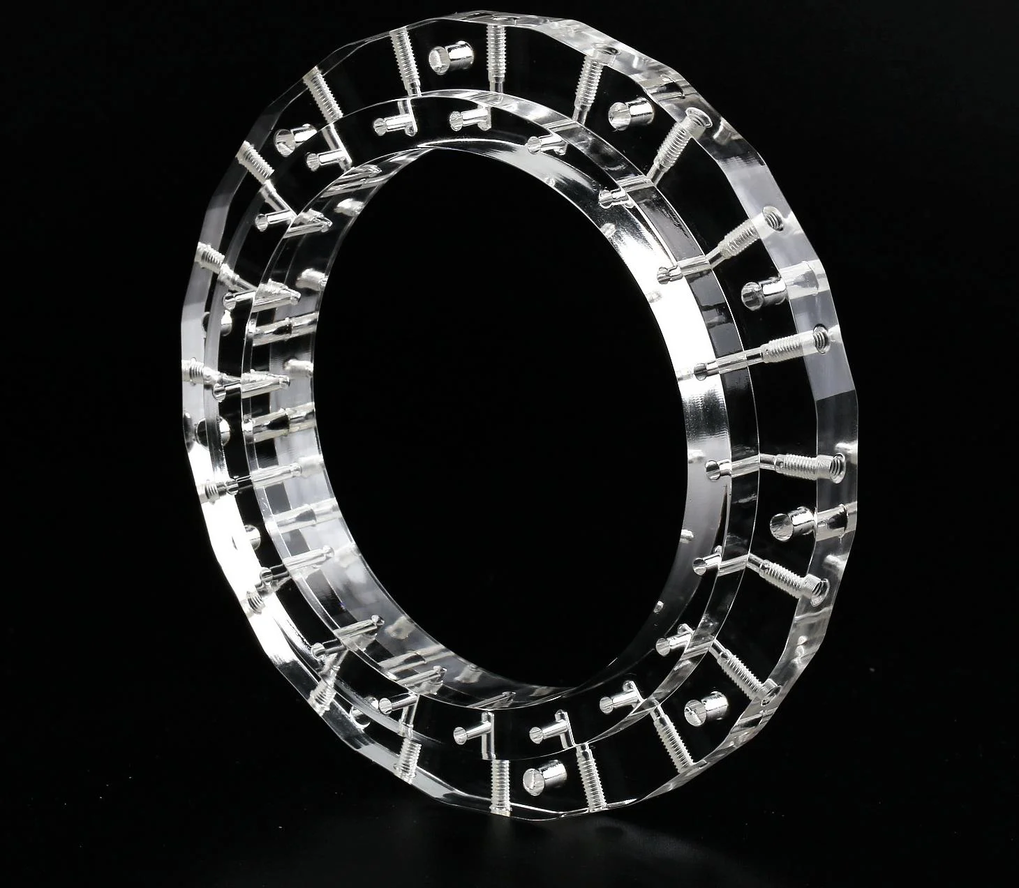
Tool marks and polishing paths
Follow the visible defect back to its source before adding polishing. Tool marks, chip scratches, chatter, and local heat can require different corrections. Finishing should be planned into the route, not used as an unlimited recovery step after the component reaches final size.
ACRYLITE’s finishing guidance distinguishes surface and edge finishing and discusses heat-induced stress. Ask which operations suit the marked region and how the supplier protects adjacent holes, sharp transitions, and mating faces.
Set a finishing allowance only after reviewing the geometry and method. The opening 0.10 mm example is an illustration, not a recommended removal value. A local change that is invisible in a photograph can still alter thickness, edge shape, or a controlled surface. Check dimensions after the final operation that can change them.
Crazing and solvent risks
Review cutting media, cleaners, polishes, adhesives, sealants, and packaging with the actual acrylic stock supplier. Crazing can make an initially clear component unacceptable after processing or exposure. Mechanical stress and chemical contact belong in the same assessment.
ACRYLITE’s machining guidance identifies heat distortion and incompatibility risks, including cutting emulsions and other contact materials. Treat those as process inputs to control. A cleaner used successfully on another transparent plastic is not automatically suitable for this grade and stress state.
Identify requirements for stress treatment, cleaning, handling, and storage where the application needs them. Confirm the actual supplier-approved sequence rather than specifying a generic cycle. Include representative post-process exposure in validation when later assembly chemicals or environmental conditions could affect the viewing region.
Table: PMMA vs PC clear parts
Compare PMMA and PC against the actual optical and structural priorities. PC can be a candidate when impact behavior dominates, while PMMA remains a candidate for a clear machined viewing component. The grade, thickness, processing, surface protection, and final acceptance still determine suitability.
| Decision | PMMA review | PC review | Acceptance evidence |
|---|---|---|---|
| Viewing quality | Stock quality, machined aperture and polish | Grade, surface condition and finishing route | Defined appearance or optical test |
| Impact requirement | Assess notch, thickness and mounting | Assess specified impact behavior and mounting | Representative component evaluation |
| Chemical contact | Confirm cleaners and process media | Confirm cleaners, coatings and process media | Grade-specific compatibility evidence |
| Critical dimensions | Allow for finishing and inspect afterward | Allow for finishing and inspect afterward | Final geometry and interface checks |
Plaskolite’s TUFFAK GP sheet data provides a product-specific PC example with identified optical and mechanical tests. Do not transfer its results to every machined PC part or use an impact comparison to establish optical suitability.
FAQ
These questions address specification details that should be settled before sample approval.
Does a polished acrylic face automatically qualify as an optical surface?
No. Polishing can improve appearance without establishing the required form, transmitted image quality, haze, or other optical characteristics. Define the functional aperture and the relevant acceptance method. Validate the finished component under the viewing or optical conditions that matter to the application.
Should every acrylic surface receive the same finish?
No. Identify viewing faces, light-entry or exit faces, mounting interfaces, and noncritical surfaces separately. Different regions may need different machining, finishing, and inspection work. Restrict polishing where it could alter a fit, edge, or functional optical geometry.
Related process selection notes
Choose a route that preserves the required aperture while producing the surrounding geometry. Leaving a suitable stock face untouched may avoid unnecessary finishing, but stock thickness, form, and surface condition still need acceptance. Machining a new face creates a different manufacturing and verification problem.
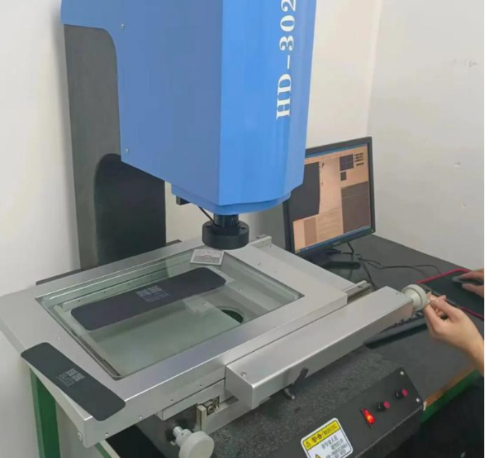
ASTM D1003 addresses haze and luminous transmittance of transparent plastics. If these characteristics matter, specify the relevant method and acceptance conditions. They do not by themselves establish surface figure, distortion, or every imaging requirement of a complete component.
For the surface-finishing review, identify the region, intended result, dimensional restrictions, and evidence required. Confirm the offered process and whether a trial sample is needed. A broad optical polish note can otherwise mean different things to the designer and fabricator.
Internal links and next steps
Provide CAD and the controlled drawing with the viewing aperture, material and stock requirements, surrounding mounting features, quantities, and the expected finish. Include controlled lighting, viewing distance, background, and defect criteria where appearance inspection forms part of acceptance.
Use the PMMA material page and CNC machining discussion to align stock, tooling, and finishing assumptions. For a consumer-electronics viewing component, supply the installed viewing and mounting conditions.
Request a 6CProto acrylic machining review with the functional aperture and acceptance criteria. Approve a representative finished sample before extending its appearance or optical result to the planned order.
FAQ
These questions address specification details that should be settled before sample approval.
Can haze and light transmission replace a visual appearance review?
They answer specific measurement questions and do not necessarily capture every visible defect or optical function. Where required, combine the applicable measurements with controlled visual criteria and a representative functional test. State the method, specimen conditions, and acceptance limits explicitly.
Is a solvent-polishing process acceptable just because the part becomes clear?
No. Review material compatibility, stress, geometry change, residues, and the later service environment. The approved process must preserve the specified interfaces and meet the required appearance or optical acceptance. Confirm the route and evidence rather than judging it only by immediate transparency.