

A drawing with a 100 mm span and a total tolerance band of 0.10 mm allows only one part in a thousand of dimensional variation. That hypothetical ratio makes inspection conditions worth discussing before cutting PEEK. Tool condition, local heating, clamping, stock history, and measurement state can all matter when turning an expensive blank into an accepted component.
Why PEEK punishes bad tooling
Plan PEEK machining around the specified grade, sharp suitable tooling, controlled chip removal, compatible cooling, stock stress history, and final inspection conditions. Review reinforced and unfilled materials separately. Establish the required dimensional state before finishing, then use representative samples to confirm the route instead of promising one tolerance for every PEEK geometry.
Begin with material identity. Unfilled, glass-reinforced, carbon-reinforced, and bearing grades are not interchangeable manufacturing inputs. Victrex’s grade-specific datasheet library illustrates why properties must be tied to a product and test condition. A generic resin family name cannot establish the finished part’s stiffness, expansion, or wear behavior.
Ask the PEEK material review to identify the proposed stock grade and form. The machining plan should address edge condition, wear monitoring, and support at vulnerable features. A tool that still removes material may already be producing an unacceptable edge or surface.
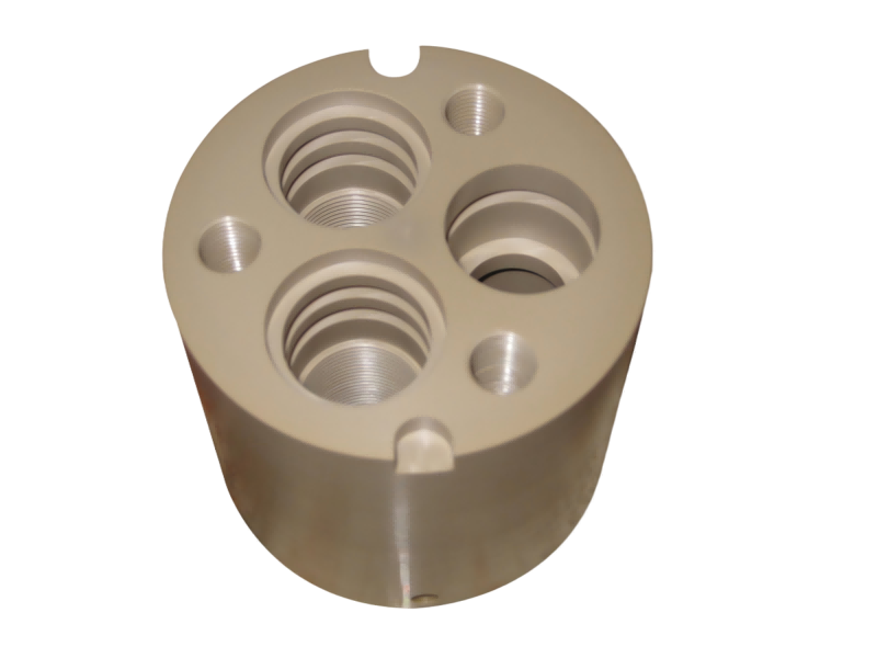
Coolant and chip control
Plan chip removal before increasing cutting speed. Trapped or recut chips can damage a surface and create local heating. Deep holes, narrow slots, and interrupted features deserve individual review; a satisfactory open-face cut does not establish that the same approach will work throughout the part.
Ensinger’s plastics-machining recommendations discuss cooling, chip evacuation, and the compatibility of process media. Use guidance for the selected material and operation. Neither a blanket dry-machining instruction nor a familiar metalworking coolant substitutes for that review.
Identify restrictions on oils, cleaning chemicals, residue, and cross-contamination in the RFQ. The intended application may make a compatible cutting fluid unsuitable as a delivered residue. Confirm how the component is cleaned and how its condition is accepted, especially when subsequent bonding, sealing, or electrical function depends on the surface.
Annealing and stress notes
Confirm the stock supplier’s processing history before prescribing extra heat treatment. Annealed starting stock can still respond to asymmetric material removal and machining-induced effects. For a deeply pocketed or close-tolerance part, ask whether the route needs intermediate stabilization and a finishing allowance.
Mitsubishi Chemical Group’s machining guide discusses roughing, annealing where appropriate, and finishing critical dimensions afterward. Apply the actual supplier’s grade- and section-specific instructions rather than copying a generic heating cycle into every PEEK order.
Release the sample from its machining restraint and assess it in the required inspection condition. A face held flat by a fixture may change after unclamping. Record any conditioning interval, thermal treatment, and final measurement state needed by the approved process. Additional annealing is a process decision to validate, not an automatic cure for poor geometry or excessive clamping.
Table: tolerance and finish practicality
Translate each tight requirement into a functional surface, a supported machining operation, and an inspection method. The practical limit depends on feature size, material, shape, temperature, and the required delivered state. Avoid a single shop-wide tolerance claim for all PEEK parts.
| Feature | Manufacturing concern | Acceptance question |
|---|---|---|
| Long overall span | Temperature and measurement state | What reference and conditioning conditions apply? |
| Thin floor or wall | Clamping deformation and release movement | Is acceptance in the free or specified restrained state? |
| Deep hole | Chip removal, tool guidance, local heat | How are size and form verified over the required depth? |
| Sealing face | Texture, form, and edge damage | Which separate controls define its function? |
| Reinforced-grade edge | Tool wear and exposed reinforcement | What edge and surface condition is acceptable? |
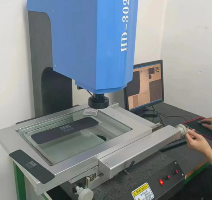
NIST’s dimensional-metrology FAQ discusses temperature and dimensional measurement. For a polymer component, agree the reference condition and suitable method rather than assuming a warm, freshly machined measurement establishes the later assembly fit.
When to mold instead of machine
Machining is a candidate for development, changing designs, small quantities, or features that suit accessible stock removal. Molding becomes a candidate when the geometry, design maturity, and repeat demand support tooling development. Compare the complete accepted-part routes, including any secondary machining.
Victrex’s PEEK injection-molding guide addresses material preparation, tooling, processing, and shrinkage. Those requirements show why transferring a machined design to a mold is an engineering project rather than a simple unit-price substitution.
Review draft, wall sections, gates, ejection, flow orientation, and the critical interfaces that may still need machining. A machined prototype does not necessarily reproduce the structure or direction-dependent behavior of a molded reinforced part. Define which prototype results remain relevant and which require production-route verification.
RFQ tips
Provide the exact grade or approved material specification, stock restrictions, CAD, drawing, quantity, critical dimensions, surface requirements, and required records. Include service temperature and relevant exposure conditions when they determine fit or material suitability. Identify cleanliness or process-media restrictions explicitly.
Use the precision-machining discussion to agree how the supplier will inspect the critical features. Ask for a proposed route and any exceptions rather than relying on a general claim that PEEK can be machined accurately.
For a first sample, select a small number of meaningful validation questions: released flatness, bore condition, representative fit, surface acceptance, and dimensional change under the specified conditions. Record the sample’s material and process history so a passing result can inform the subsequent production order.
FAQ
These questions address specification details that should be settled before sample approval.
Does every PEEK part need additional annealing?
No. Review the stock history, selected grade, geometry, removal sequence, and required dimensional stability. Some demanding parts may benefit from an agreed intermediate treatment, but its cycle and place in the route should follow supplier guidance and validation. Do not assume that extra heating corrects every machining problem.
Can the same process be used for unfilled and reinforced PEEK?
It should be reviewed rather than assumed. Reinforcement changes machining and surface considerations, including tool wear and edge condition. Specify the actual grade, assess representative features, and agree the required finish and inspection criteria before approving production.
What does a tight PEEK tolerance need beyond a drawing number?
It needs a defined feature, material, inspection state, suitable measurement method, and relevant conditioning requirements. The manufacturing route must account for support, heat, and released geometry. Validate the required interface with representative samples rather than extending a general tolerance claim to every shape.
Related process selection notes
Implement the project in a controlled order: confirm grade and stock; review geometry and tooling; settle cooling and cleaning; agree any stabilization; finish and inspect in the specified state; then approve the representative sample. Close open items before treating the quotation as a manufacturing instruction.
The CNC machining review should connect process choices with acceptance evidence. Where a requirement is uncertain, request a trial or a documented limitation. Neither a successful cut nor an attractive surface establishes long-term dimensional stability for an untested assembly.
Request a 6CProto PEEK machining review with grade, geometry, and inspection conditions. Include the interfaces that actually determine success so tooling and stabilization decisions serve a clear requirement.