

A gear blank and a mold cavity both end up as hardened steel, but the machining conversation starts before the part is hard. Hardened steel parts — dies, molds, gears, shafts, and wear components — are specified in the hardened state because service life depends on it, so the real decision is a route decision: machine soft, harden, and finish with grinding or EDM, or machine the finished part directly in the hardened state with hard turning and hard milling. Each route carries different distortion, tooling, and surface-integrity consequences, and the right choice depends on the geometry, the target hardness, and which features actually matter in service.
The Two Routes to a Hardened Part
The traditional route machines the part in the annealed or pre-hardened state, heat treats it to the target hardness, and then finishes the critical surfaces with grinding or EDM. Soft machining is fast, tooling is inexpensive, and chip control is straightforward, which is why most hardened components still start this way. The catch is that heat treatment moves the material: distortion, scaling, and phase changes alter the geometry, so the finish operation must remove that distortion and bring the critical features back to tolerance.
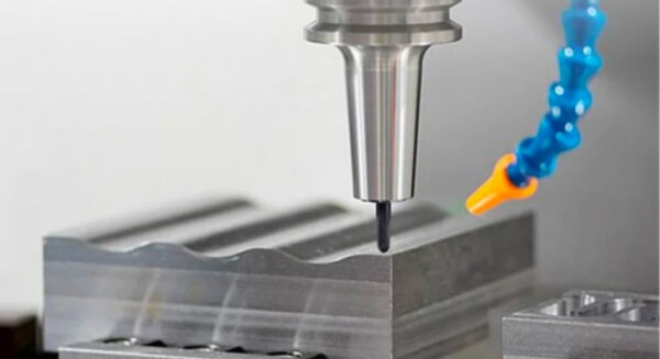
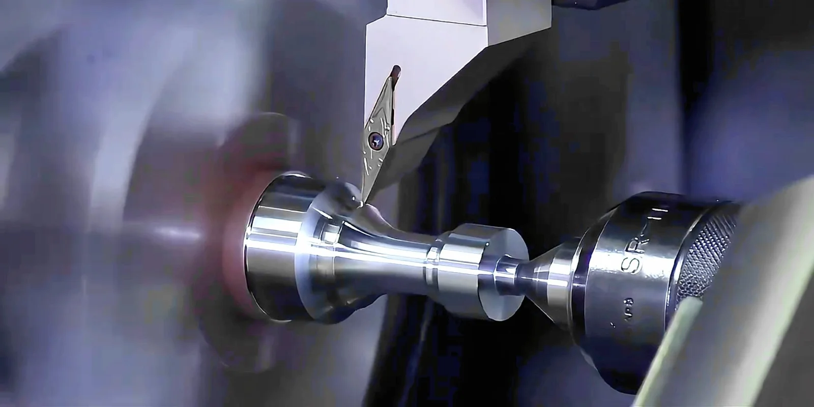
The direct route hard-machines the part in its hardened state. Hard turning cuts hardened diameters with CBN or ceramic inserts, while hard milling cuts dies and molds with coated carbide or CBN end mills, producing finished surfaces without a separate grinding setup. The advantages are fewer setups and no distortion to correct, because the part is cut in its final state. The costs are specialized tooling, slower material removal, and a process window that demands real machine rigidity.
| Route | When it fits | The risk to manage |
|---|---|---|
| Soft machine → harden → grind / EDM | Tight bores, large parts, interrupted geometry | Heat-treatment distortion and extra setups |
| Hard turning | Finished diameters and faces in the hardened state | Process window, surface integrity |
| Hard milling | Dies, molds, complex 3D surfaces | Tool reach, corner radii, tool life |
How the Route Decision Is Made
The route decision matters most for tight bores, interrupted geometry, and fatigue-critical surfaces. A hardened shaft with a tight bore is usually soft-machined, hardened, and ground, because a bore tolerance at tenths of a millimetre sits outside the practical hard-machining window. A mold cavity with complex detail is usually hard-milled, because the distortion to correct and the second setup would cost more than the hard milling itself. And a gear or shaft that carries cyclic load needs a surface-integrity plan regardless of route, because the white layer is the failure mode that a dimensional drawing never shows.
Hardness verification is part of the finish route, not an afterthought. The heat treater’s report and the supplier’s hardness test confirm the part is in the specified range before the finish operation, because hard-machining parameters and grinding-wheel selection both depend on the actual hardness. The drawing should state the hardness range and the verification method, and the first article should record the measured values alongside the dimensions. Our CNC machining service applies the same drawing discipline across soft and hardened work, and the CNC machining materials guide is a useful reference for the steel grades that typically run through both routes.
Stock and Distortion Planning
The soft-machine route lives or dies by the stock left for the finish operation. Heat treatment moves the part, and the finish stock must be large enough to clean up the distortion but small enough that the finish operation is not grinding away excessive hardened material. The drawing should separate soft-machined features from hardened-finish features and call out the finish stock explicitly, because the heat treater and the grinder need to work from the same picture.
Distortion is directional and part-specific. Long, slender parts bow; thin-wall parts warp; and asymmetric sections move differently from symmetric ones, so the distortion allowance should be based on the geometry and the material’s heat-treatment response rather than a general rule. The practical approach is to machine the critical features, harden, and then verify the distortion on the first article, adjusting the stock for the next lot. The first article is the calibration point for the whole process — the measured shift between the as-machined and as-hardened condition becomes the working allowance.
The drawing should also state the hardness range, not just the grade. A range of 48–52 HRC and a range of 58–62 HRC are different machining problems, and the finish route — hard machine or grind — depends on the actual hardness. The hardness callout belongs with the finish sequence so that quoting matches the drawing. Standards such as ISO standards for tolerances help keep the dimensioning consistent, but the hardness and stock callouts are a project decision.
Hard Milling vs. EDM: The Mold and Die Boundary
Hard milling and EDM are the two routes to finished detail in hardened tool steel, and the boundary between them is geometry. Hard milling cuts complex 3D surfaces directly with end mills, producing the cavity or contour without a separate electrode, and it is the modern standard for mold and die finishing. EDM — electrical discharge machining — erodes the material with electrical sparks from a shaped electrode, and it wins where a milling cutter cannot reach: sharp internal corners, deep narrow slots, and detail with very small radii.
The design rule follows the boundary. Internal corners should use the largest radius the design allows, because small radii force small tools that wear fast in hardened steel, and radii below the practical milling range push the feature to EDM, adding the electrode and its cost. A mold cavity with 0.5 mm corner radii is an EDM feature; the same cavity with 3 mm radii is a hard-milling feature. The corner-radius decision is therefore a cost decision made on the drawing, before any metal is cut. Our CNC milling page explains how these geometry limits shape quotable work.
Surface Integrity: The White Layer and Residual Stress
Surface integrity is where hard-machined parts are won or lost. Abusive cutting, excessive heat, or a dull tool can leave a white layer — a thin, hard, re-hardened or re-cast surface layer with micro-cracks — on the machined surface. The white layer is a crack-initiation site under fatigue, and it can appear in both hard machining and EDM, so the finish parameters and the inspection method matter for parts that carry cyclic load.
The controls are process parameters, tool condition, and verification. Finishing passes should use a light depth of cut with a sharp tool and sufficient coolant, because the last pass defines the surface. Residual stress behaviour should be considered in the same review: a grind that works in one direction can leave a different residual-stress pattern than the same grind in another, which matters for press-fit or fatigue-loaded features. Inspection should confirm the finish removed the prior-operation damage before the part leaves the machine. Where a hard-machined finish is needed, the surface finishing service page covers the options that protect rather than damage the surface.
First-Article Verification Before the Lot
Whether the route is soft-machine-then-finish or direct hard machining, the first article is where assumptions get checked. Plan the distortion allowance from the first-article data rather than from a general rule. Use the largest internal radii the design allows to keep features hard-millable, and reserve EDM for radii and detail below the practical milling range. Call out surface integrity on fatigue-critical features with the finish-pass strategy, and confirm the datum and measurement method — hardened parts need the same measurement discipline as the cutting.
Getting the first article right also frames the quoting exercise. A drawing that states hardness range, finish stock, radii, and surface-integrity requirements produces comparable quotes, because every supplier is pricing the same process. Our practical guide to CNC machining tolerances walks through how drawing callouts translate into achievable results, and the industrial equipment industry page shows where hardened tooling and wear parts end up in service.
Conclusion
Hardened steel machining is a route decision: machine soft, harden, and finish with grinding or EDM, or machine directly in the hardened state with hard turning and milling. Plan the finish stock against the distortion, use the largest practical radii to keep detail hard-millable, and protect surface integrity on fatigue-critical features. The part that survives service is the one whose route, stock, and surface plan were decided on the drawing.
FAQs
How much stock should be left before hardening?
Enough to clean up the heat-treatment distortion on the critical features, but not so much that the finish operation grinds away excessive hardened material. The allowance depends on the geometry and the material’s response, so machine the critical features, harden, verify the distortion on the first article, and adjust for the next lot.
How much does heat treatment distort a machined part?
The amount depends on geometry, material, and heat-treatment cycle. Long, slender parts bow; thin-wall parts warp; and asymmetric sections move differently from symmetric ones. The finish stock must cover the distortion, and the first article after hardening is the calibration point for the allowance.
When is EDM better than hard milling?
When a milling cutter cannot reach the detail: sharp internal corners, deep narrow slots, and radii below the practical milling range. EDM adds an electrode and its cost, so the drawing should use the largest radii the design allows and reserve EDM for the geometry that requires it.
What is the white layer and why does it matter?
The white layer is a thin, hard, re-hardened or re-cast surface layer with micro-cracks left by abusive cutting or EDM. It is a crack-initiation site under fatigue, so fatigue-critical parts need controlled finish passes and a surface-integrity requirement on the drawing, because a dimensional drawing does not show it.