

A small, thin heat-treated part needs its hardness verified, and the shop’s Rockwell tester cannot measure it — the part is too thin for the load, and the indentation would break through or read the anvil instead of the part. The hardness test must fit the part: Rockwell for the fast shop-floor check on parts of adequate thickness, Brinell for coarse surfaces and large sections, and Vickers for small parts, thin sections, and case depths. Choosing the test by the part is the first step in hardness verification, and the drawing should carry the test that the part can actually support.
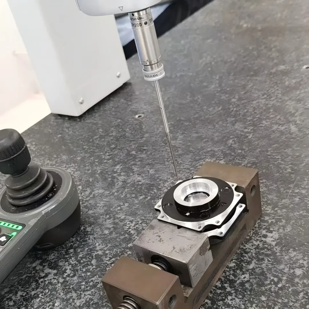
Rockwell: fast shop-floor testing and its limits
Rockwell is the workhorse of shop-floor hardness testing: it is fast, direct-reading, and suitable for production and receiving inspection on parts of adequate thickness. The Rockwell scales use different indenters and loads for different hardness ranges, with the common scales lettered for their application. The limits are the part size and the surface: Rockwell needs a minimum thickness so the indentation does not read through, a clean and flat surface for the indentation, and a part that is not damaged by the test. A small or thin part that cannot meet the Rockwell requirements needs a different test. The Rockwell test is the right choice when the part supports it, and it is the fastest way to verify the material condition in production.
The Rockwell scale should be selected for the hardness range, and the drawing should specify the scale with the value, because a value on the wrong scale is meaningless.
Brinell: coarse surfaces and large parts
Brinell uses a large ball indenter and a heavy load, producing a large indentation that averages the material over a wider area. The test suits coarse surfaces, large sections, and cast or forged parts where the microstructure varies, and it is common in the metals that Rockwell does not serve well at the low end of the hardness range. The Brinell indentation is large and may be unacceptable on finished or cosmetic parts, and the test is slower than Rockwell. Brinell is the choice when the part is large and the surface is coarse, and the hardness is verified over an area that represents the material. The test method and the load should be specified with the value.
The Brinell indentation leaves a visible mark, and the test location should be agreed where the part’s appearance or its finish matters.
Vickers: small parts, thin sections, and case depth
Vickers uses a diamond indenter with a range of loads, making it the flexible test for small parts, thin sections, and case-hardened surfaces. The small indentation suits parts that cannot take the Rockwell or the Brinell mark, and the load can be reduced for thin sections and for measuring the hardness profile through a case. Vickers is the test for the fine work that the other methods cannot reach, and it is the standard for case-depth and micro-hardness measurements. The trade is the preparation and the measurement: the Vickers indentation is small and must be measured with a microscope, and the surface must be prepared for the reading. Vickers is the choice when the part or the measurement demands the fine scale.
The Vickers load should be chosen for the section, and the measurement method and the conversion should be confirmed with the standard.
Choosing the test by material, size, and spec
The test selection follows the material, the size, and the specification. The material and its hardness range select the scale; the part size and the thickness select the test and the load; and the specification or the standard may require a specific test. The selection should be reviewed against the part: a thin case-hardened surface needs Vickers at a low load, a large cast section suits Brinell, and a production steel part of adequate thickness suits Rockwell. The drawing should name the test with the value, and the inspection should use the method the drawing specifies. The test that fits the part is the test that produces the trustworthy reading.
The test location and the surface condition should also be specified, because a hardness reading at the wrong location or on an unprepared surface does not represent the part.
Putting hardness requirements on drawings
The hardness callout should carry the test, the scale or the method, the value or the range, and the location: for example “Rockwell C 28–32 HRC at the marked location.” The drawing should note the part’s minimum thickness where the test requires it, and the inspection report should state the method, the load, and the result. The hardness requirement that is complete is enforceable, and the certificate or the report provides the evidence. The factory-equipment article covers the tools; this page is the test-selection decision that makes the hardness callout executable. When the test fits the part and the callout is complete, the hardness verification is a routine check rather than a dispute.
Running the hardness verification in practice
The hardness verification in practice follows the method the drawing specifies. The inspector confirms the test and the scale, prepares the surface at the specified location, and runs the indentation with the calibrated tester. The reading is recorded with the scale, the load, and the location, and the result is compared against the acceptance range. The verification should also check the tester’s calibration and the part’s minimum thickness, because a reading from an uncalibrated tester or a too-thin part does not represent the material. The inspection record ties the hardness to the lot and the heat-treatment batch, so the result is traceable. A hardness verification that follows the method is a check that both sides can trust; one that improvises the scale or the location produces a number that neither side can defend.
The verification should be repeated at the interval that matches the risk: a first article and a sampling plan for the production lots, with the frequency set by the process stability and the part’s criticality. When a reading falls near the limit, the verification should be repeated or confirmed on the specified scale, because the conversion uncertainty can change the decision. The records should be kept with the part, so the hardness history is available for the review and the audit. When the hardness verification is run with the method and the record, the hardness requirement is enforced — and the part that passes is the part whose condition is confirmed.
The hardness test selection should also be reviewed with the part’s drawing and its acceptance standard. The drawing should name the test and the location that the supplier will verify, and the acceptance standard should state the value, the range, and the method with the part’s geometry in view. A part that is too thin for the Rockwell test, or too small for the Brinell indentation, needs the drawing to specify the Vickers method and the load before the supplier quotes and tests it. The review should confirm that the specified test can be run on the actual part without damaging it, and that the location is accessible and representative. When the test and the acceptance are specified with the part’s geometry, the hardness verification is a repeatable check that both sides can perform and trust; one that is left to the tester’s choice produces results that vary with the tester and the method. The drawing and the test plan together make the hardness requirement enforceable, and the review that connects them is the review that prevents the scale dispute at the first inspection.
Keep the hardness method and the acceptance record with the part, so the test is repeatable by the supplier and the buyer. The record is the reference for the audit and the review when the material or the heat treatment changes.
Confirm the hardness method with the supplier before the order, and state it on the PO with the value and the location. The agreed method prevents the scale dispute at the first inspection, and it is the reference that the supplier and the buyer both test against.
Match the test to the part, state it on the drawing, and verify it with the report — then the hardness requirement is a check, not a dispute.
Confirm the test and the scale with the supplier before the order, and state the method and the location on the PO so the acceptance is verified the same way at both ends.
Verify the tester’s calibration and the surface preparation with the first reading, and record the method, the load, and the location with the result so the hardness is repeatable across the supplier and the buyer.
Verify the hardness method and the calibration with the first reading, and confirm the report’s scale, load, and location before the acceptance is signed.
If you are specifying or verifying hardness on a metal part and want the test and the scale matched to your geometry, the 6CProto quality team can work from your part and your material to the hardness method and the acceptance plan.